Tr4aJim
-
Content Count
566 -
Joined
-
Last visited
About Tr4aJim

Recent Profile Visitors
1,510 profile views


-
Jeff, I have MX5 leather seats from a ‘95 SE. These are the low back style with separate head rests. Unfortunately this style are rare as dragon teeth. Jim
-
Peter, yes I did the “drop test” a few years ago and found the pistons were in the wrong chambers. Jim
-
Bob, Success! I found a small thin washer that I cut in half. The notched bronze shaft now has a very positive engagement of the cable. Thanks! Jim Rob, I will set the fast idle tomorrow. Actually I’m going to do the full procedure (per the SU manual) of setting the jets, balancing the SUs, and setting the idle. cheers, Jim
-
Bob approximately how “deep” should the half-moon piece be? Jim
-
Ian, thanks, but unfortunately that seller doesn’t ship to the US (and even if they did, the price plus shipping, is usually close to what I find here). Bob, the “spares box” cable does have the spring steel clip on it. I was able to pry it apart slightly and slide it out of the way. Underneath was a small slot, but that’s it. I assume the “half moon” plate you mention should have been in that slot, and hence why that cable was in my spares box! I’ll try and fabricate something, but as you say, it’s very small. cheers Jim
-
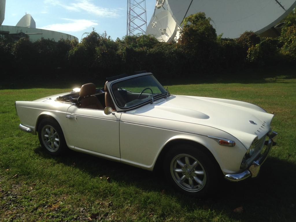
Update- 1 - I may have found the cause of the original idling issue. I checked the fast idle screws and found they both were backed way off, not touching the cam at any point. I also found that both were loose in their fittings, so they may have simply backed off from vibration. I’ll put a tiny dab of lock tight on the threads so that can’t happen again. 2 - I checked on eBay and the cables are no cheaper than on Moss However after rooting through my old spares box, I found separate choke cable inner and outer sections. The notched brass part of the inner cable looks in good shape
-
Ah that’s what I like to hear - an agricultural solution!! Jim PS - I just checked on MOSS and WOW you weren’t kidding! - $90!!!!!!! eBay here I come!
-
Bob, yeah the choke lever on my car is much the same. You pull it to the desired position, then rotate it to lock it there. However on my cable, rotating the knob appears to lock the cable at any place on its travel. I can’t feel any distinct positions that would indicate if “full choke” (moving jets) or “partial choke” (engaging fast idle cam), is engaged. Yet I checked and the choke rod does have the notches you mentioned. Are these notches supposed to indicate the two choke positions? If so, then it appears the spring loaded plate you mention for engaging these notches is broken/mi
-
Thanks Rob. I will check the position of the fast idle screw/cam. One other thing - should I be able to feel a “detent” when pushing in on the choke knob shaft, where the motion changes from moving the jets, to just moving the fast idle cams? I have to guess at the correct position for fast idle only, roughly moving the knob half way in from being fully pulled out. Jim
-
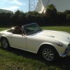
Folks, I’ve been noticing a weird behavior while driving my 4A lately (HS6 carbs). The car starts fine with choke, and runs well (no smoke, no stumble). When the temp comes up, I release the choke, and the car continues to run well. However if the car goes back to idle, for example at a traffic light, the rpm’s drop precipitously to 200-100 rpm where I think the engine might stall. So I blip the throttle until the I’m moving again, and the car again runs fine. Yet the rpms will continue to drop with fear of stalling at idle as before. However after driving for 20 minutes or so, when I’m
-
Rob, I wonder if the change in my 4A light switch wiring was to prevent the issue you showed? Jim
-
Folks, just an FYI that I believe I’ve mentioned before. Several 4A owners here in the US (myself included) have found slightly different lighting switch wiring for the “flash to pass” feature. I have attached my crude hand drawn sketch I made at the time, as well as an updated wiring diagram made by a member of the US Triumph forum (#15 is the lighting switch, #16 is the dip switch, and the different wiring is in blue). My car is a ‘65. We never did determine why some of our cars were wired in this way (maybe US market?) and others match the Autowire diagram. Anyway just a heads up.
-
Great, thanks! I guess I’ll try an 8amp fuse in the horn circuit. Jim
-
Rob, ok I will move the horn off the ignition switch. Would plugging it into the connector that joins the alternator and ammeter be ok, or is a direct connection to the battery better? Oh, and the stock horn inline fuse (35) is in place. Jim
-
Thanks guys! Rob, that explanation of fuse “theory” is very helpful! I can see now that I have to resize (lower) the fuse ratings I have installed. However I’m not sure I understand Ian and Roger’s comments regarding adding relays. I have attached a diagram I made a while ago after I installed the headlight relays. I haven’t had a chance to update it yet, so I just drew in the hazard switch. Besides the relays I have for the headlights, where else should I install relays? BTW, originally the PO had wired the horn directly to the battery when he installed the alternator, and re