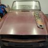
PodOne Posted November 22, 2022 Report Share Posted November 22, 2022 Evening all I was hoping someone local might have come forward to give a hand but it looks like I'm going to have to attempt this solo. So as ever its over to you good folks on here for some advice as I go along armed with the Brown Book and Triumph Repair Manual so be gentle! My experience has been with 4 pots and a lap top so the mechanical PI is completely new. All the PI components have been reconditioned by Neil Ferguson and the Dizzy from Martin at Dizzy Doc who fitted it with electronic ignition both many moons ago. First instalment. Cylinders No 1 and No 6 at TDC with No 1 on its firing stroke with its valves on the rock (no valve rock at No 6) as per picture. The crank pulley TDC marking and pointer are in perfect alignment as determined when the short block was built by the engine builder. The head was built up by me. Next task was to install the pedestal to allow me to next work out the end float. It took a lot of trial and error (mainly error) to get the gearing shaft to engage the oil pump fully and sit far enough down to get the pedestal body to contact the block. The best position I could get compared to the Brown Book illustration is as shown in the picture. Is this close enough? If the drive is in the correct position is there another way of working out the end float as using a washer as per Brown Book may see it falling off and into the sump. Any tips appreciated. Once the end float is determined how should I proceed? Thanks all Andy Quote Link to post Share on other sites
poolboy Posted November 22, 2022 Report Share Posted November 22, 2022 If the valves are 'on the rock' that piston is not at the Top of it's firing (compression) stroke...It's completing the up exhaust stroke and beginning the intake down stroke. At TDC of the compression stroke, both valves are completely closed Quote Link to post Share on other sites
john.r.davies Posted November 22, 2022 Report Share Posted November 22, 2022 8 minutes ago, poolboy said: If the valves are 'on the rock' that piston is not at the Top of it's firing (compression) stroke...It's completing the up exhaust stroke and beginning the intake down stroke. At TDC of the compression stroke, both valves are completely closed Quote Link to post Share on other sites
john.r.davies Posted November 22, 2022 Report Share Posted November 22, 2022 PodOne, you have misunderstood the "Equal Lift on Overlap" method of cam timing! At TDC and No.1 cylinder on the firing stroke, the valves are indeed both closed, but for a considerable range of rotation. No point can be used as a marker. But on No.6, at TDC, the two valves are indeed 'on the rock' with the inlet opening and the exhaust closing. At TDC, they should be both open by the same, small amount. I'm on my phone right now. When I get to my PC, I'll post a link to my article about ELoO on Sideways, and on a more recently found and simpler method of determining that 'equal lift' moment. Hope that helps! John Quote Link to post Share on other sites
John L Posted November 22, 2022 Report Share Posted November 22, 2022 Is it a CP engine or a CR?, as the MU is timed slightly differently on each. John, Surely the cam has already been timed? As a matter of interest do you know which camshaft you have, a brand new one or the original? John Quote Link to post Share on other sites
john.r.davies Posted November 22, 2022 Report Share Posted November 22, 2022 For PodOne, see my article https://sideways-technologies.co.uk/forums/index.php?/topic/7770-equal-lift-on-overlap-the-other-cam-timing-method/#comment-102165 And for the recent simpler method: https://sideways-technologies.co.uk/forums/index.php?/topic/9639-a-new-method-of-cam-timing/#comment-134275 Please post for further explanation. John L, All standard Triumph (or Standard-Triumph!) camshafts were 'symmetrical' and may be timed by ELoO. Most 'hot' camshafts are too, only some very extreme ones are not. And yes, I only skimmed Andy PodOne's OP, and so misunderstood his needs! His camshaft is timed - now he needs to time the M/u. Andy, With No.1 at TDC, the Brown book provides the directions for setting up the M/u. It's trial and error, because as you fit the M/u, the internal rotor is turned. You need to insert a finger into the barrel to turn the pinion back by a suitable amount before mounting it, so that the No.6 orifice is at or just before full opening when mounted. If you get desperate, please contact me, I'm only t'other side of t'Pennines! John Quote Link to post Share on other sites
PodOne Posted November 23, 2022 Author Report Share Posted November 23, 2022 Thanks all for your feed back. Just for clarification and to clarify my terminology of the term "on the rock" which I may have used incorrectly. Engine is the original 1969 CP motor which to save time I had the engine builder build up the block/short motor with a new OEM standard cam (not reground) purchased from Chris Witor. John D; I gave the engine builder the link to your method of timing the cam to look at but in fairness to them they had been in business 50 years they had classic cars of their own and came recommended by a few other formites so I guess/hope they knew what to do! The cam has been timed. The TDC mark on the crank pulley should be accurate and from memory matched the mark made by the builder on the flywheel and I did check with a dial gauge just to be sure. With the crank pulley set at TDC the valves on No 1 are fully closed as the rocker arms can "rock" there is no contact so on the firing stroke, with he the plugs out I can see the piston tops on both No 1 and No 6 as was the case with the head removed. The valves on No 6 are in contact with the rocker arms. So as per the original pic is the slot close enough? Andy Quote Link to post Share on other sites
john.r.davies Posted November 23, 2022 Report Share Posted November 23, 2022 Andy, "With the crank pulley set at TDC the valves on No 1 are fully closed as the rocker arms can "rock" there is no contact so on the firing stroke, with he the plugs out I can see the piston tops on both No 1 and No 6 as was the case with the head removed. The valves on No 6 are in contact with the rocker arms." So you have the engine at TDC, with No.1 on firing stroke. The precise test is, are both No.6 valves equally lifted? I would say that you have the slot on the drive cog correctly positioned. I have a tube with a slot cut in the end that matches the dog on the end of the oil pump drive shaft. I use this to adjust the position of the dog, so that I can insert the drive cog into mesh with the camshaft gear with that slot in the correct position. There isn't a big difference between the drive cog in position, and not, so I check with a depth gauge. The absolute position is not critical, as shown by the Brown Bible's acceptance of a M/u rotor that that shows the orifice anywhere between a sliver and fully open, but not past that point. I wouldn't have been so cheeky as to tell your engine builder how to time the camshaft! But ELoO is a well established method, that is recommended in the Brown Bible as an alternative. My method using a spirit level is new, IMHO! Quote Link to post Share on other sites
ntc Posted November 23, 2022 Report Share Posted November 23, 2022 1 hour ago, PodOne said: Thanks all for your feed back. Just for clarification and to clarify my terminology of the term "on the rock" which I may have used incorrectly. Engine is the original 1969 CP motor which to save time I had the engine builder build up the block/short motor with a new OEM standard cam (not reground) purchased from Chris Witor. John D; I gave the engine builder the link to your method of timing the cam to look at but in fairness to them they had been in business 50 years they had classic cars of their own and came recommended by a few other formites so I guess/hope they knew what to do! The cam has been timed. The TDC mark on the crank pulley should be accurate and from memory matched the mark made by the builder on the flywheel and I did check with a dial gauge just to be sure. With the crank pulley set at TDC the valves on No 1 are fully closed as the rocker arms can "rock" there is no contact so on the firing stroke, with he the plugs out I can see the piston tops on both No 1 and No 6 as was the case with the head removed. The valves on No 6 are in contact with the rocker arms. So as per the original pic is the slot close enough? Andy Andy Your timing is correct just check the angle of the plastic drive key, you basically mount the pedestal and check the clearance using a sacrificial feeler and then use the amount of caskets required Quote Link to post Share on other sites
BRINDUS44 Posted November 23, 2022 Report Share Posted November 23, 2022 Andy, The drive slot is OK - one tooth either way will just give a different position for your rotor arm and so a different position of the distributor body when points (?) are opening no. 1 firing. If the distributor body is too far clockwise the tacho cable can restrict rotation. Why not just sit the distributor onto the slot and see where the body ends up with rotor pointing at no.1 contact in dizzy cap? Ian Quote Link to post Share on other sites
PodOne Posted November 23, 2022 Author Report Share Posted November 23, 2022 Thanks all for the feedback. I'll work out the end float and move on to fitting the MU and no doubt report back! Neil are you able to bend a feeler gauge to 90 degrees and get it under the cog? Andy Quote Link to post Share on other sites
ntc Posted November 23, 2022 Report Share Posted November 23, 2022 20 minutes ago, PodOne said: Thanks all for the feedback. I'll work out the end float and move on to fitting the MU and no doubt report back! Neil are you able to bend a feeler gauge to 90 degrees and get it under the cog? Andy Andy If you don’t like removing the pedestal try with the thick casket first then use nose pliers and lift the drive to make sure you have clearance it’s when you have none the cam drive will self destruct. Quote Link to post Share on other sites
PodOne Posted December 3, 2022 Author Report Share Posted December 3, 2022 (edited) Hi folks After another read of the brown book, and Lucas PI service manual along with a review of this thread and peoples advice I gave it a dry run today and I think its come out ok. First the distributor was fitted and the rotor points to number confirming the drive is in the correct position. The pedestal MU drive slot in the manuals say should be vertical I couldn't achieve it perfectly attached to the engine. How critical is vertical as the pedestal and MU will be mated up off the car? y So next up was fitting the pedestal to the MU with the pedestal off the engine with the MU scribe lines aligned and with the drain hole at the bottom. Is this just a way of putting the hole in port 6 in the fully open position which it was? Following the adjustment advice (the pedestal shaft was very tight anticlockwise) I was able to get the port to just start opening and can be seen in the pic. Overall am I on the right track before I attach the injector pipes? Thanks Andy Edited December 3, 2022 by PodOne Quote Link to post Share on other sites
john.r.davies Posted December 3, 2022 Report Share Posted December 3, 2022 Keep going on that bearing, Andy! Quote Link to post Share on other sites
PodOne Posted December 4, 2022 Author Report Share Posted December 4, 2022 12 hours ago, john.r.davies said: Keep going on that bearing, Andy! Thanks John. Quote Link to post Share on other sites
PodOne Posted December 4, 2022 Author Report Share Posted December 4, 2022 Well folks after a frustrating afternoon of now sore fingers and setting the pedestal end float (one gasket) as per Neils suggestion can I for the life of me get the No 6 port to look like what I achieved only yesterday ie just opening like in the pic above. The best I can get is a now full hole or one of the other undesirable positions following the brown book adjustment advice. I've tried moving the pedestal slot from facing No 9 Push rod to more towards No 10 no better. Also when the rotor just disappears I've tried varying amounts of anti clock rotation; nothing close. Split the pedestal and MU no issues seen there. The best I can get is still a full hole. It's as though the gearing is too course to allow port alignment. More likely I'm doing something daft. Any suggestions or is a full hole acceptable with No 1 set at TDC and firing. Can see why folk go EFI !! Thanks Andy Quote Link to post Share on other sites
Mick Forey Posted December 4, 2022 Report Share Posted December 4, 2022 There has been a lot of good quality research over many years on the effect of direct and indirect fuel injection timing on pistons engines for both automotive and aviation. The overall conclusion is that with direct injection (into the cylinder) timing is absolutely critical. However, with indirect injection (into the inlet manifold) timing makes very little difference to anything. Mick Quote Link to post Share on other sites
john.r.davies Posted December 4, 2022 Report Share Posted December 4, 2022 That's confirmed by the Brown Bible's instructions (my post above). I think you're fine with a full hole, Ian. John Quote Link to post Share on other sites
ntc Posted December 4, 2022 Report Share Posted December 4, 2022 39 minutes ago, PodOne said: Well folks after a frustrating afternoon of now sore fingers and setting the pedestal end float (one gasket) as per Neils suggestion can I for the life of me get the No 6 port to look like what I achieved only yesterday ie just opening like in the pic above. The best I can get is a now full hole or one of the other undesirable positions following the brown book adjustment advice. I've tried moving the pedestal slot from facing No 9 Push rod to more towards No 10 no better. Also when the rotor just disappears I've tried varying amounts of anti clock rotation; nothing close. Split the pedestal and MU no issues seen there. The best I can get is still a full hole. It's as though the gearing is too course to allow port alignment. More likely I'm doing something daft. Any suggestions or is a full hole acceptable with No 1 set at TDC and firing. Can see why folk go EFI !! Thanks Andy You should be fine with that and nice to see a dizzy in the correct place. Quote Link to post Share on other sites
PodOne Posted December 4, 2022 Author Report Share Posted December 4, 2022 Thanks John, Mick and Neil. I should have paid more attention to your post John! I'll nurse my fingers which have a nice impression of the pedestal engraved in them and button it up next weekend. Andy Quote Link to post Share on other sites

Recommended Posts
Join the conversation
You can post now and register later. If you have an account, sign in now to post with your account.