Adrian Fuller Posted September 26, 2021 Report Share Posted September 26, 2021 I am moving onto the cam chain, when I removed the original crank sprocket there were no shimms (no 81 on moss engine plate). Am I correct that these would only be needed to set up the cam and crank sprocket ie. Parallel? Many thanks in advance Quote Link to post Share on other sites
iain Posted September 26, 2021 Report Share Posted September 26, 2021 The shims are for alignment, once the cam/front bearing end float up is set correctly. Iain Quote Link to post Share on other sites
Adrian Fuller Posted September 27, 2021 Author Report Share Posted September 27, 2021 Having set up the shimms crank and camshaft sprockets I notice that the manual suggests using DAG colloidal graphite and soaking the cam end bearing in it when warm. Is this required on the original bearing cap whick I have cleaned with panel wipe? . I have used lashings of cam lube but dag is obviously different. Thanks in advance for any suggestios Quote Link to post Share on other sites
Motorsport Mickey Posted September 27, 2021 Report Share Posted September 27, 2021 When fitting a new camshaft and followers ALWAYS use the lube material they suggest (or supply in some cases), no matter what any manual or previous experience tells you otherwise works. If you don't and the camshaft looses a lobe or seizes within a short time frame the camshaft suppliers will swear blind it's because you didn't follow their lubrication instructions. Mick Richards Quote Link to post Share on other sites
Adrian Fuller Posted September 27, 2021 Author Report Share Posted September 27, 2021 Hi I am trying to finf the correct torque for the camshaft end bearing bolts, is it the same as the end plate bolts.. 14 to 16 ft/lbs? Quote Link to post Share on other sites
Lebro Posted September 27, 2021 Report Share Posted September 27, 2021 Manual does not seem to specify, but if 1/4" unf bolts, then yes, same as cover Bob Quote Link to post Share on other sites
Adrian Fuller Posted October 1, 2021 Author Report Share Posted October 1, 2021 Hi after too many hours setting the valve timing for my Newman PH1 cam I believe I have it as close as I am going to get it. Do the following figures look OK. Max lift on cam no1 is achieved at 111 deg with no movement down until 116 deg. Cam lift @TDC =0.040“ @10 deg ATDC= 0.060". I have tried moving camshaft chainwheel and flipping it which only takes readings further away from spec on Newman cam spec sheet below. Are these figures acceptable or am I missing something?. Thanks in advace Quote Link to post Share on other sites
Adrian Fuller Posted October 1, 2021 Author Report Share Posted October 1, 2021 And for clarity I am measuring directly off the cam follower Ta Quote Link to post Share on other sites
BlueTR3A-5EKT Posted October 1, 2021 Report Share Posted October 1, 2021 (edited) Use the 2 nd cam lobe from the front as that is the inlet. Just in case…… have read this? https://www.macysgarage.com/cam degree.htm Edited October 1, 2021 by BlueTR3A-5EKT Quote Link to post Share on other sites
Adrian Fuller Posted October 1, 2021 Author Report Share Posted October 1, 2021 Hi That is the one I used Thanks Quote Link to post Share on other sites
Adrian Fuller Posted October 4, 2021 Author Report Share Posted October 4, 2021 Eventually contacted Newman cams best figures I could get were approximatly 97deg 106 or 113. They were very quick to respond and put me in touch with a very knowledge chap who agreed that best figure would be 106 cam rocking as this also gives 57" a Tdc. So after many days this is what I am going with... Not sure if this does anything to ignition timing but will deal with that when I get there. Quote Link to post Share on other sites
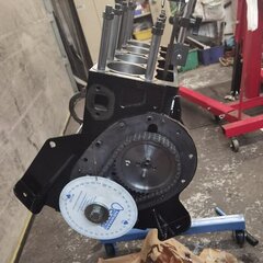
Adrian Fuller Posted October 4, 2021 Author Report Share Posted October 4, 2021 Questions just don't stop. I am now fitting narrow belt pulley kit and thought I should just confirm that I still use the oil deflector {no 79 moss plate} after the carnkshart chain wheel and do I just use bearing tool to fit the collar onto narrow bel pulley as it it a "good" fit. See photo below Thanks All Quote Link to post Share on other sites
Ian Vincent Posted October 4, 2021 Report Share Posted October 4, 2021 it never needs to come off again so I would have thought a drop of Loctite 270 wouldn't hurt. A suggestion: Once you have turned the engine to TDC and trial fitted the pulley, mark off the position of TDC on the outside of the pulley where it aligns with your timing case pointer. Then remove the pulley and cut or score a series of perpendicular lines at ten degree intervals around the perimeter either side of TDC with a hacksaw with (I would suggest) a deeper one for TDC that you can fill with white paint. It makes the subsequent task of setting the timing that much easier. Oh and yes, I did still fit the oil thrower (deflector) inside the timing cover with the convex side facing away from the engine and towards the oil seal. Rgds Ian Quote Link to post Share on other sites
Lebro Posted October 4, 2021 Report Share Posted October 4, 2021 (edited) Yes, you still need the oil deflector, & yes, just press the sleeve onto the pulley. A press is ideal, otherwise a vice, or just drift it on , keeping it straight as it goes. Bob. P.S. Agree with Ian about timing marks, I put a series of grooves in mine - 0°, then 5°, 10°, 15°, 20° 25°, & 30° I made the 0,10,20 & 30 grooves longer than the inbetween ones. Edited October 4, 2021 by Lebro Quote Link to post Share on other sites
Adrian Fuller Posted October 4, 2021 Author Report Share Posted October 4, 2021 Started to set up tinting marks on crankshaft pulley. I am assuming that I have the pulley fully home (see picture) are you marking Tdc etc on the thicker ind of the pulley and any tricks to avoid parallax error? Quote Link to post Share on other sites
Ian Vincent Posted October 4, 2021 Report Share Posted October 4, 2021 (edited) To avoid parallax error I have bent the pointer down so that the tip is only a half a mm or so above the edge of the pulley. Rgds Ian PS having identified TDC I marked my pulley when it was off the engine. I made a cardboard template the same diameter as the pulley and marked it up using my camshaft timing protractor. It was an easy job to transfer the marks to the pulley. Edited October 4, 2021 by Ian Vincent Quote Link to post Share on other sites
Adrian Fuller Posted October 4, 2021 Author Report Share Posted October 4, 2021 Timing marks sorted, last question (I hope, how full of oil is the timing chain cover as I cannot see a return so Is klingerite gasket on cover standoff bolt a good idea? Quote Link to post Share on other sites
Ian Vincent Posted October 4, 2021 Report Share Posted October 4, 2021 Adrian, I have my oil deflector the other way round with the dish facing outwards. I just used a fibre washer. Rgds Ian Quote Link to post Share on other sites
iain Posted October 4, 2021 Report Share Posted October 4, 2021 I think Adrian’s orientation is correct? Iain Quote Link to post Share on other sites
Ian Vincent Posted October 4, 2021 Report Share Posted October 4, 2021 I searched the web and found this diagram. I also found this which I believe is an extract from the TR4 manual. Rgds Ian Quote Link to post Share on other sites
Adrian Fuller Posted October 4, 2021 Author Report Share Posted October 4, 2021 That's fantastic work, thanks Ian. I may make a slightly thicker washer for the extended attachment as I have used quite thin klingerite gasket material. Quote Link to post Share on other sites
Lebro Posted October 4, 2021 Report Share Posted October 4, 2021 From the TR2-3A service manual: "Fit the chain tensioner to it's pin and secure with washer and split pin. Screw in timing cover support bolt to the engine plate and fit the oil deflector to the crankshaft so that the raised edge faces the timing cover" I used a fibre washer on the support bolt. Bob. Quote Link to post Share on other sites
Adrian Fuller Posted October 5, 2021 Author Report Share Posted October 5, 2021 Looked through my motor strip down photos looks like concave points towards the timing chain cover Quote Link to post Share on other sites
Ian Vincent Posted October 5, 2021 Report Share Posted October 5, 2021 (edited) Clearly that is the right answer. As is taking lots of photos as you take things apart, (and put them back together). Rgds Ian Edited October 5, 2021 by Ian Vincent Quote Link to post Share on other sites

Recommended Posts
Join the conversation
You can post now and register later. If you have an account, sign in now to post with your account.