Richard V Posted January 11, 2009 Report Share Posted January 11, 2009 Hi, I am trying to fit a Moss anti roll bar to my TR4 at the moment, and I was wondering if someone would be able to tell me what the external dimension between the two bumper support brackets should be where they meet the chassis, i.e. where the ARB should go. I think I have 4A brackets fitted to my 4, but the only differance I can see is a step on the inner face of the bracket. The holes in the valance line up well, so I think that they are "interchangable" with 4 brackets. My problem is that at 690mm bend to bend, the Moss ARB seems a bit narrow to fit round the brackets, which are 690 to 700mm across in this area (spread to align with valance). I know of the old problem with this Moss part, mine is a new one with the 890mm hole to hole dimension. Any help greatly appreciated, Richard. Quote Link to post Share on other sites
Richard V Posted January 12, 2009 Author Report Share Posted January 12, 2009 (edited) Hi, I am trying to fit a Moss anti roll bar to my TR4 at the moment, and I was wondering if someone would be able to tell me what the external dimension between the two bumper support brackets should be where they meet the chassis, i.e. where the ARB should go. I think I have 4A brackets fitted to my 4, but the only differance I can see is a step on the inner face of the bracket. The holes in the valance line up well, so I think that they are "interchangable" with 4 brackets. My problem is that at 690mm bend to bend, the Moss ARB seems a bit narrow to fit round the brackets, which are 690 to 700mm across in this area (spread to align with valance). I know of the old problem with this Moss part, mine is a new one with the 890mm hole to hole dimension. Any help greatly appreciated, Richard. Help. I have now contacted 2 forum members who have successfully fitted or "dry fitted" the same bar as mine (TT3181). I have Jeff from Moss on the case who has checked the full Moss stock and assures me that all bars are 690mm bend to bend. He is now checking the drawing and will get back to me. He also tells me that they have sold 20 of these ARB kits so expects the bar to be correct. This leaves me with a chassis, bumper bar or valance problem. I admit my chassis is rubbish, it measures 625mm across the outer faces of the main members. (blue manuel quotes 619mm at this point) so 6mm bigger. But this does not account for the fact that the distance across the bumper bars where the ARB fits is 710mm which clearly won't accept a bar which is 690mm. The hole to hole dimension of the mounts on the front valance is 775mm Should the bumper bars be parallel to each other or spreading out as mine are? Richard. Edited January 12, 2009 by Richard V Quote Link to post Share on other sites
TorontoTim Posted January 14, 2009 Report Share Posted January 14, 2009 Hi Richard, I've just fitted one of these ARB's to my 1961 '4 (after a few problems - sorted out remotely with Jeff). I'll do some measuring of bumper irons, etc. tomorrow and let you know how it all measures up on mine if that's helpful...? Tim Quote Link to post Share on other sites
Richard V Posted January 14, 2009 Author Report Share Posted January 14, 2009 Hi Richard, I've just fitted one of these ARB's to my 1961 '4 (after a few problems - sorted out remotely with Jeff). I'll do some measuring of bumper irons, etc. tomorrow and let you know how it all measures up on mine if that's helpful...? Tim Fantastic, This ARB is driving me mad, I realy dont see how it can fit.... Thanks Tim, cant wait. Richard. Quote Link to post Share on other sites
TorontoTim Posted January 14, 2009 Report Share Posted January 14, 2009 (edited) Ok, measuring across the outer edges of the "flanges" on the bumper irons is c. 675mm. I measured this width with the tape flush with the front end of the chassis legs. In my case, then, it's quite a tight tolerance, but I can fit a finger between the ARB and the bumper iron on each side. FYI, my chassis measures c. 615mm outer edge to outer edge at the point the bumper irons mount to it. The irons on my 4 also kick out as they extend forwards but I have no way of knowing if they are original 4 parts, or 4A (unless they are not interchangeable, of course). I notice that there are different part numbers for these irons from 4 to 4A, but I don't know what the difference actually is - I presume that marque specialists could tell you - unless someone on the forum knows... I have photos of my ARB in situ - let me know your email address if you'd like to see them; they are too big to upload here. Hope this helps. Tim Edited January 14, 2009 by TorontoTim Quote Link to post Share on other sites
Richard V Posted January 14, 2009 Author Report Share Posted January 14, 2009 (edited) Ok, measuring across the outer edges of the "flanges" on the bumper irons is c. 675mm. I measured this width with the tape flush with the front end of the chassis legs. In my case, then, it's quite a tight tolerance, but I can fit a finger between the ARB and the bumper iron on each side. FYI, my chassis measures c. 615mm outer edge to outer edge at the point the bumper irons mount to it. The irons on my 4 also kick out as they extend forwards but I have no way of knowing if they are original 4 parts, or 4A (unless they are not interchangeable, of course). I notice that there are different part numbers for these irons from 4 to 4A, but I don't know what the difference actually is - I presume that marque specialists could tell you - unless someone on the forum knows... I have photos of my ARB in situ - let me know your email address if you'd like to see them; they are too big to upload here. Hope this helps. Tim Thanks Tim, Very interesting. Firstly, If I take the dimension from the TR workshop manual, the chassis is quoted as 619.2mm (2 x 30.96cm) outer edge to outer edge at this point. Next, the bumper iron has a small step in the face which bolts to the chassis member. This step requires a 2mm packer plate to ensure that the iron sits flat on the chassis member. So in addition to this additional 4mm there are the 2 "U" section bumper irons themselves, at 30mm each in width at this point. Now add to the equasion the fact that a 3/4 inch ARB is never going to be a perfect right angle in the forward bent section, the clamps can not be positioned hard up to the bend. About 16mm inboard seems as close as I can get them, before they start to take an angle which will overstress the installation. (Sounds like my 16mm is the same as your "but I can fit a finger between the ARB and the bumper iron on each side". So in theory, a grand total of 683mm for the clearance. My ARB measures 690mm across the inside of the front bar, bend to bend. So it is tight, and the 30mm wide clamps will not sit on the center line of the bumper irons as intended, due to the bend radius. My chassis is slightly wider for some reason 625mm, which gives me a total of 690mm at a point just aft of the front end of the chassis members. Due to the outward cant of the irons, which starts just after the chassis members, the position where the poly bushes and the fixing clamps should sit, is 700 to 705mm over the length of the clamp. All this adds up to an ARB which will not fit my car as intended......ARB under high load, touching the bumper bars and the clamps sitting inboard of them with nothing to bolt to. The only solution I can see is to make a bespoke sump guard to which I can bolt the ARB clamps in a more comfortable, inboard, position and cut material out of the lower flange of the bumper iron to provide clearance for the ARB as it bends rearwards to the wishbones. Jeff at Moss tells me that 20 of these new bars have been sold and that all their stock is conform to the drawings at 690mm. I know you were partly involved in pushing for the production of this new bar, so I would be interested to have your opinion on this problem. Best regards, Richard. Message sent with my Email for the pictures which I would love to see. Edited January 14, 2009 by Richard V Quote Link to post Share on other sites
TorontoTim Posted January 21, 2009 Report Share Posted January 21, 2009 (edited) Apologies for the delay in replying - PC issues... I trust that you received the photos that I sent - I hope they were helpful. I wasn't actually involved in the development of this ARB although I had a bit of discussion with Jeff @ Moss about fitting it. As a result of the delay and the weather now in Toronto, I haven't driven the car in anger since fitting it. However, based on your measurements (both theoretical and actual) I would say that the ARB is VERY low in tolerance, at best. It is probably worth talking to other suppliers to get the dimensions and fitting methods of their ARB's. Revington TR is no doubt (considerably?) more expensive, but their stuff has generally been tested in real-world competition situations which mean that it's very likely to be robust and have development kinks ironed out. As ever, you pays yer money and takes yer choice... Edited January 21, 2009 by TorontoTim Quote Link to post Share on other sites
JJC Posted January 21, 2009 Report Share Posted January 21, 2009 Ok, measuring across the outer edges of the "flanges" on the bumper irons is c. 675mm. I measured this width with the tape flush with the front end of the chassis legs. In my case, then, it's quite a tight tolerance, but I can fit a finger between the ARB and the bumper iron on each side. FYI, my chassis measures c. 615mm outer edge to outer edge at the point the bumper irons mount to it. The irons on my 4 also kick out as they extend forwards but I have no way of knowing if they are original 4 parts, or 4A (unless they are not interchangeable, of course). I notice that there are different part numbers for these irons from 4 to 4A, but I don't know what the difference actually is - I presume that marque specialists could tell you - unless someone on the forum knows... I have photos of my ARB in situ - let me know your email address if you'd like to see them; they are too big to upload here. Hope this helps. Tim I think 4 and 4a are different because I bought what I thought was a TR4 bumper on ebay and the holes for bolting to the irons didn't line up with irons. It turned out to be a TR4a bumper which has different spacings of the holes in the bumper and hence the support irons are different. From memory I think it's the inner ones. At least that's how it looked, could be completely wrong of course......... JJC Quote Link to post Share on other sites
Richard V Posted January 22, 2009 Author Report Share Posted January 22, 2009 Hi, Thanks for the feedback guys. Tim, the picture was exactly what I needed to see, it proves that the bar can be successfully fitted to a TR4 with what I imagine is a standard front end. Your clamps are very close to the bends, but well possitioned on the bumper irons. However they look flat and without any deformation of the polybush. Either your bar has a sharper bend radius or the clamps are under alot of tension. Jeff at Moss did tell me that the bar had to be as narrow as possible to prevent clearance issues with larger wheel and tyre combinations. This I understand, but as you say the tollerance is very low and it seems that my car falls outside this tollerance. At the moment I have put the bar to one side whilst I complete the suspension rebuild and I will look at a modification to the bumper irons or a sump guard when I am finished. JJC, Thanks for your info, I did wonder if this was a possibility, and dispite a few questions on the TR5/250 forum I am no further forward. I know that the front of my car was involved in an accident in an earlier life but I do not know the extent of the damage or what parts were replaced. So it is possible that 4A parts were used. I know that a trip to the international in the summer will provide me with all the info I need on the subject, but untill then, can anyone tell me what the distance between the two bumper mounting holes in the front valance should be on an early TR4? (Mine is 775mm) Or, how to identify a bumper iron as being from a 4 or 4A. Best regards, Richard. Quote Link to post Share on other sites
JJC Posted January 22, 2009 Report Share Posted January 22, 2009 Hi, Thanks for the feedback guys. Tim, the picture was exactly what I needed to see, it proves that the bar can be successfully fitted to a TR4 with what I imagine is a standard front end. Your clamps are very close to the bends, but well possitioned on the bumper irons. However they look flat and without any deformation of the polybush. Either your bar has a sharper bend radius or the clamps are under alot of tension. Jeff at Moss did tell me that the bar had to be as narrow as possible to prevent clearance issues with larger wheel and tyre combinations. This I understand, but as you say the tollerance is very low and it seems that my car falls outside this tollerance. At the moment I have put the bar to one side whilst I complete the suspension rebuild and I will look at a modification to the bumper irons or a sump guard when I am finished. JJC, Thanks for your info, I did wonder if this was a possibility, and dispite a few questions on the TR5/250 forum I am no further forward. I know that the front of my car was involved in an accident in an earlier life but I do not know the extent of the damage or what parts were replaced. So it is possible that 4A parts were used. I know that a trip to the international in the summer will provide me with all the info I need on the subject, but untill then, can anyone tell me what the distance between the two bumper mounting holes in the front valance should be on an early TR4? (Mine is 775mm) Or, how to identify a bumper iron as being from a 4 or 4A. Best regards, Richard. Richard - went down to the garage in the rain to look for my original TR4 bumper. Unfortuantely I've just tidied up the loft and the old bumpers are under other stuff and I'm not sure if I was pulling out the TR2 bumper or the TR4 one. So I went and measured the one I think is a TR4a one on the car. There are three holes each side in the bumper blade. The two holes furthest from the ends look to me to be about 19cm apart on the 4a and 25.5 apart on the 4. Just for interest the overider goes on the inner hole on the 4 and the middle one of the three on the 4a. End of my knowledge. Except (!) i doubt if the support irons are any different apart from having the middle hole in a slightly different place! Best regards JJC Quote Link to post Share on other sites
88V8 Posted January 23, 2009 Report Share Posted January 23, 2009 ....the bumper iron has a small step in the face which bolts to the chassis member. This step requires a 2mm packer plate to ensure that the iron sits flat on the chassis member. I'm not familiar with the 4, but I can tell you that the 6 bumper iron - which I suspect is the same as the 4A - has a step in the inner face to accomodate the radiator skid. The side flanges of the skid fit in that step between the iron and the chassis. So could you fit a skid from a 4A or 6, and bolt the mounts of the ARB to that, which is the standard arrangement for the 6 ? Ivor Quote Link to post Share on other sites
Richard V Posted January 23, 2009 Author Report Share Posted January 23, 2009 Hi, JJC - I think we are talking at crossed purposes. My question is for the two bumper support brackets that run from the front of the chassis rails up to the vallance. The dimension I am interested to know it between the 2 holes in the front vallance to which the bumper assembly is bolted. I think you are describing the 2 u shaped brackest which run horizontaly from the vallance to the chromed bumper itself. I am interested to know if the hole pitch between the two holes in the front vallance si different between a TR4 or 4A Ivor - I think you have provided me with an important peice of my puzzle. My bumper support brackets have the steps that you talk about. So I am sure these are 4A or later. As there is nothing to fit under this step on my car I made 2mm packer plates so that the brackets sit flat on the chassis rail when the bolts are tightened. I now need to know if I have the correct TR4 front vallance fitted or not. If someone can measure across the bolt pitch on the vallance it would be of great help. Thanks. I guess that the TR6 ARB is slightly wider to accomodate this added step. As Tim said the TR4 ARB is very low tollerance and does not accept any slight increase in width. Regards, Richard. Quote Link to post Share on other sites
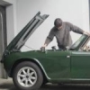
TR NIALL Posted January 23, 2009 Report Share Posted January 23, 2009 I think if we had some photos of the brackets and area we might be able to solve this problem quicker. Quote Link to post Share on other sites
Richard V Posted January 23, 2009 Author Report Share Posted January 23, 2009 (edited) Niall, You really are right, I should have thought of that sooner. You know when you have looked at something for long enough, you imagine everyone knows what you are talking about. So here are the photos. 1st one shows the bracket on the RH side of the car. 2nd shows the bolt which passes through the valence, and you can just see the same bolt on the LH side. It is the distance between the two bolts that I need to know for 4 and 4A. 3rd one shows the LH bumper support bracket removed from the car. My apologies. Richard. Edited January 23, 2009 by Richard V Quote Link to post Share on other sites
Smokey Posted January 24, 2009 Report Share Posted January 24, 2009 Hi Richard, I measured the distance c/c between the two bolts on my 1962 TR4, and it is approximately 780 mm. I say approximately because it's -15C in the garage and it's difficult to get behind the bumper to measure. Hope that helps. I have an original factory ARB on my car, which I had a local racing shop fabricate from drawings provided by a helpful TR Register member. I installed it by following the factory instructions, but it's too low and thus easily damaged, so I may raise the mounts, which attach to the bumper support brackets shown in your photos. Quote Link to post Share on other sites
stuart Posted January 24, 2009 Report Share Posted January 24, 2009 Centre to centre of the holes in the front panel is thirty and a half inches. Richard your irons are definitely TR4a/5. I dont have a 4 around to get any pics of the brackets but the 4 ones are beefier and flat on the face that abuts the chassis. Stuart. Quote Link to post Share on other sites
Richard V Posted January 24, 2009 Author Report Share Posted January 24, 2009 Hi, Thanks to all of you, for the info. I will be looking for a new set of TR4 bumper irons, in the knowledge that the front panel is correct. Once the front end is built up, I will continue with the ARB. But at the rate Im going, that will be the summer. Thanks again, Richard. For the ongoing saga of my front suspension, see new post! Quote Link to post Share on other sites
Smokey Posted January 24, 2009 Report Share Posted January 24, 2009 Hi Richard, I know this is a long way for you, but I've gotten some very obscure parts from Scott Harper at Team Triumph in Ohio. He is very helpful. Quote Link to post Share on other sites
RAHTR4 Posted January 25, 2009 Report Share Posted January 25, 2009 Richard, Looking at your photos I think that you have the correct TR4 bumper support brackets fitted to your car. Today I have dug out some parts and taken the attached photo, as you can see the 4 and 4A brackets are very different in shape and chassis bolting positions, plus they have different offset bends to the bumper fixing hole. The TR4 part has the shallower offset bend, from the contact face that bolts to the chassis to centre of the hole that holds the bumper is 75mm. On the TR4A part this dimension of 92mm. If you need any other measurements or photos let me know as all the parts are now at hand in the garage. Regards, Richard Quote Link to post Share on other sites
Richard V Posted January 26, 2009 Author Report Share Posted January 26, 2009 Hi, What I do know: 1. The bumper irons that are fitted to my car are exactly the same as the upper example in your great picture (Thanks for going to this effort Richard. Yes, 75mm offset as per your description). Ivor and Stuart both say these are for TR4A and later. 2. My chassis, body tub and front valance (with 775mm hole spacing) are all 1962 TR4 parts. 3. My bumper irons are bolted to the outer face of the front chassis box section. 4. Checking against TR4 show cars in the Piggot books, my bumper is a TR4 model (with overriders mounted inboard of the headlights.) 5. When I recieved the car, the bumber irons (with their 2mm deep stepped contact face) were bolted directly to the chassis therefore only touching the chassis in two small areas, due to the step. I re-installed them with 2mm steel packers under this step to give a more solid installation with contact over the full area of the iron/chassis contact area. What I dont know: 1. I would go with Stuart and Ivor's logic of having a flat face to contact the chassis rail on the TR4. However I see from some pictures sent by Tim, or others that I took at Malvern, other 4's have the stepped version (Yes it was me taking pictures under your wheel arches last year ). So Why would a bumper iron be stepped for a 4 (no shims illustrated in Moss catalogue or Triumph parts catalogue) ? 2. Why is my chassis 625mm across its outer faces (Tim's is 615mm)? (Both radiator and cross tube fit fine, with only about 2mm of movement at the turret tops as I tighten the cross tube.) 3. With bumper irons fitted, their offset gives me a width of 700 to 710mm across the outer face of the 2 irons in the area where a 690mm ARB should fit. 20 of these ARB's have been sold by Moss. I have pictures and feedback of 2 of them fitted to TR4's with about 8mm clearance either side of the ARB, Why not mine? Help! Richard. Quote Link to post Share on other sites
Rhodri Posted January 26, 2009 Report Share Posted January 26, 2009 My TR4 is fitted with the top one, also. Quote Link to post Share on other sites
stuart Posted January 26, 2009 Report Share Posted January 26, 2009 Hi, What I do know: 1. The bumper irons that are fitted to my car are exactly the same as the upper example in your great picture (Thanks for going to this effort Richard. Yes, 75mm offset as per your description). Ivor and Stuart both say these are for TR4A and later. 2. My chassis, body tub and front valance (with 775mm hole spacing) are all 1962 TR4 parts. 3. My bumper irons are bolted to the outer face of the front chassis box section. 4. Checking against TR4 show cars in the Piggot books, my bumper is a TR4 model (with overriders mounted inboard of the headlights.) 5. When I recieved the car, the bumber irons (with their 2mm deep stepped contact face) were bolted directly to the chassis therefore only touching the chassis in two small areas, due to the step. I re-installed them with 2mm steel packers under this step to give a more solid installation with contact over the full area of the iron/chassis contact area. What I dont know: 1. I would go with Stuart and Ivor's logic of having a flat face to contact the chassis rail on the TR4. However I see from some pictures sent by Tim, or others that I took at Malvern, other 4's have the stepped version (Yes it was me taking pictures under your wheel arches last year ). So Why would a bumper iron be stepped for a 4 (no shims illustrated in Moss catalogue or Triumph parts catalogue) ? 2. Why is my chassis 625mm across its outer faces (Tim's is 615mm)? (Both radiator and cross tube fit fine, with only about 2mm of movement at the turret tops as I tighten the cross tube.) 3. With bumper irons fitted, their offset gives me a width of 700 to 710mm across the outer face of the 2 irons in the area where a 690mm ARB should fit. 20 of these ARB's have been sold by Moss. I have pictures and feedback of 2 of them fitted to TR4's with about 8mm clearance either side of the ARB, Why not mine? Help! Richard. Richard I notice you dont have a radiator protection shield in place.Have you tried one as the bolt holes should line up with the captives in the front ends of your chassis legs. This may give you some idea of the actual "spread" difference on your chassis. Early 4 chassis can be a bit variable similar to the differences in early 2 chassis. Is the "spread" the same one side to the other from the actual centre line of the chassis and does it look as if the extra outer box section at the front end of the chassis has ever been replaced on either side as this also may give some clue where the extra width has come from. You say you have about 2mm of pull in when fitting the turret cross tube, is that either side or total as this also may give an indication of some "spread" of the front end. As to the irons having a step in I havent got a 4 here to compare so cant shed any light on that. The 3a irons have a step to accomodate the rad shield bolt and are of similar shape to the 4 ones as its essentially the same chassis but widened. I wonder if thats what you have. Stuart. Quote Link to post Share on other sites
Smokey Posted January 26, 2009 Report Share Posted January 26, 2009 Richard, Looking at your photos I think that you have the correct TR4 bumper support brackets fitted to your car. Today I have dug out some parts and taken the attached photo, as you can see the 4 and 4A brackets are very different in shape and chassis bolting positions, plus they have different offset bends to the bumper fixing hole. The TR4 part has the shallower offset bend, from the contact face that bolts to the chassis to centre of the hole that holds the bumper is 75mm. On the TR4A part this dimension of 92mm. If you need any other measurements or photos let me know as all the parts are now at hand in the garage. Regards, Richard We seem to have a range of opinions here as to which is TR4 and which is TR4A, but it seems in comparing pictures of the cars, the bumper on a TR4A is higher (on the valance) than the bumper on the TR4. This seems reasonable, given that the TR4A over-riders are much shorter. Is it possible that the top one in the picture is the TR4A one, given that it puts the bumper higher and closer to the valance? Quote Link to post Share on other sites
RAHTR4 Posted January 26, 2009 Report Share Posted January 26, 2009 Richard, As another check I have measured the chassis of my TR4 and it has an overall width of 615mm. The distance between the centrelines of the two bolt holes in the lower front valance is 775mm. The top bracket as shown in my photo, marked TR4, is a perfect fit from the chassis to the hole in the lower front valance. Each bracket has got a step in it and this is to make it clear the return edge of the end cap which is welded to the end of each chassis rail. I have fitted a large penny washer into the small gap to keep the bracket alignment correct. The TR4A bumper support brackets have the same step for the same reason. Rest assured the two brackets on your car are the correct TR4 type. If you need any other checks done just let me know. Regards, Richard Quote Link to post Share on other sites
Richard V Posted February 8, 2009 Author Report Share Posted February 8, 2009 Richard, As another check I have measured the chassis of my TR4 and it has an overall width of 615mm. The distance between the centrelines of the two bolt holes in the lower front valance is 775mm. The top bracket as shown in my photo, marked TR4, is a perfect fit from the chassis to the hole in the lower front valance. Each bracket has got a step in it and this is to make it clear the return edge of the end cap which is welded to the end of each chassis rail. I have fitted a large penny washer into the small gap to keep the bracket alignment correct. The TR4A bumper support brackets have the same step for the same reason. Rest assured the two brackets on your car are the correct TR4 type. If you need any other checks done just let me know. Regards, Richard Thanks for all the help on this subject and the PM's, pictures etc. I have now established that all of you out there have chassis widths of between 615mm and 619mm, (as per the blue book). Now that I have paint stripped, sanded, blasted the front of the chassis I have discovered that the cross beam has been removed and re-welded on the LH side at some point in time. The same accident seems to have done quite a bit of damage to the chassis rail which is patched up. All this gives me a wider chassis than normal. The new Moss ARB is a good product, and really looks great. I wish I could fit it to my car but its just not possible. (congratulations to Moss for this quality / affordable part) After a call to Revington, (yes Neil does answer the phone himself, and is just as friendly as everyone says.) I have a second hand Revington ARB on its way to me, which at 720mm wide should do the job nicely, and will not require cutting or welding of my TR4 bumper bars. Just shows that things work out in the end, and that it would be no fun if everything worked first time around Again many thanks, Richard. Quote Link to post Share on other sites

Recommended Posts
Join the conversation
You can post now and register later. If you have an account, sign in now to post with your account.