1968 TR5 Restoration 7 – UPB 4F – Dave McDonald
May 2020 - July 2020
Engine Preparation
Straight after the body shell and panels were delivered to the welder on 26th May 2020 for the replacement floors, etc I started to concentrate on the engine, stripping it for a complete rebuild.
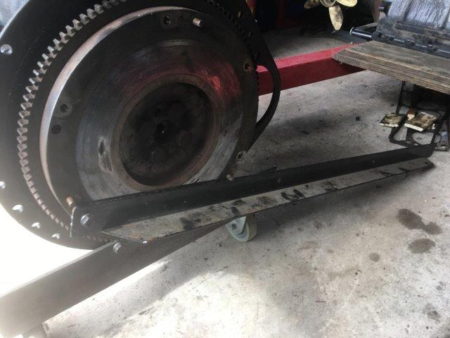
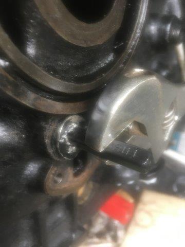
The front damper bolt was stubborn to remove, requiring a 40 x 40mm angle to be fixed to the flywheel to provide resistance and my 2 foot long cracking bar on the socket at the front.
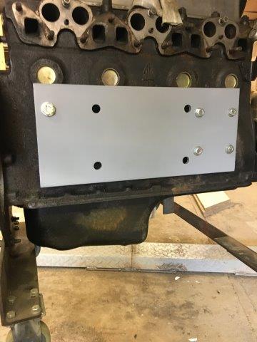
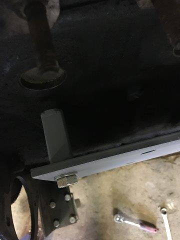
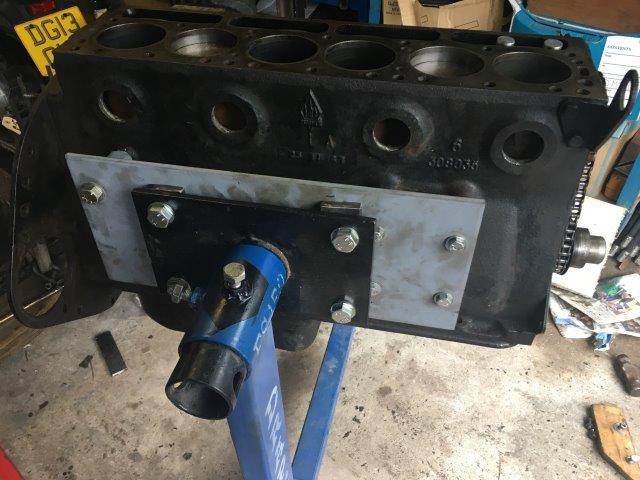
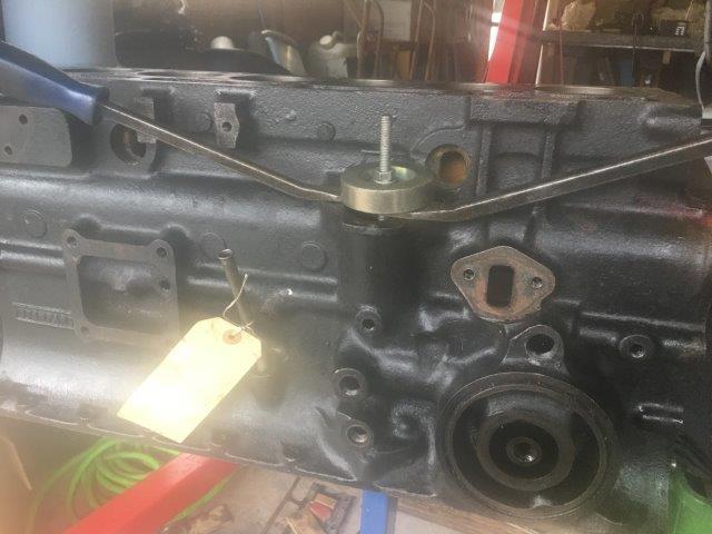
Like most examples I think, my engine stand was deigned to attach to the back end of the block. The long 6 cylinder block thus sticks out a long way. Whilst it’s never tipped overit has always looked a bit unsteady to me. I had this plate made up to attach to the relatively flat right side of the block so that it rotates through an axis across the block instead of along the block. It attaches to the 4 fixings for the engine mounting bracket and one extra bolt where the water jacket drain is located.
Removing the cylinder head revealed heavy carbon deposits on the pistons and in the combustion chambers. The “coppery” colour on the valves is, I understand, a result of the head not having an unleaded fuel conversion and using an unleaded fuel additive. I’ve used Millers VSP in every fill throughout the 23 years of my ownership. The engine had been rebuilt in 1993 by Jowett Man during the previous restoration, so I was surprised to find standard bore pistons, although even now there was no evidence of major wear in the bores.
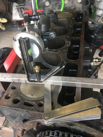
After cleaning up the piston tops I checked the piston clearances to the top of the block as I intended to have the block decked to ensure it was flat and wanted to be sure there was sufficient clearance. See below.
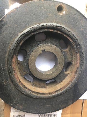
The damper when removed showed what appeared to be a very perished rubber, see below. Who would have thought it, it’s only 52 years old. I sought views on whether to reuse or replace on the Forum and, as is often the case, got varying views. I decided to replace with new from Moss – more of that later.
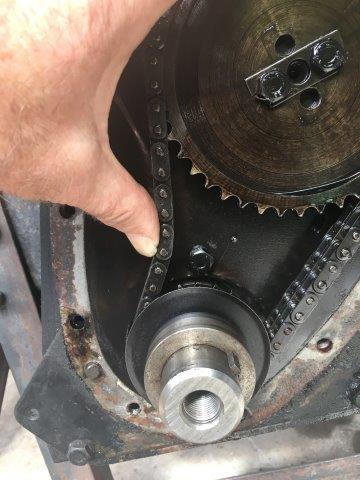
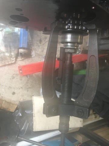
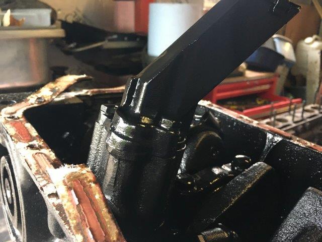
With the timing cover removed it was clear the timing chain was stretched. A replacement timing set was ordered with new chain, crank sprocket and cam sprocket. The crank sprocket was removed using my Dads’ old puller – unknown vintage but still works well.
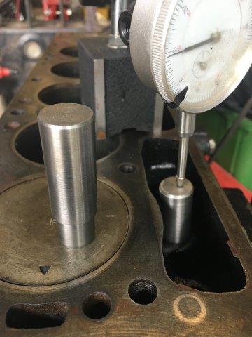
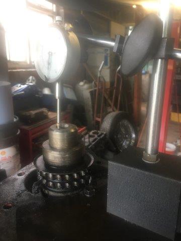
I’ve always been a bit disappointed with the TR5 performance and have wondered about the cam that was in it for some time. Before I removed the cam, simply for my own interest, I checked the lobe lifts. I used a dial gauge with a temporary spacer in each cam follower. See below. 0.Recorded lifts of 0.220” were less than the expected 0.250” and I suspected worn lobes – I’ve heard tales of poorly made cams wearing prematurely from various quarters. When the camshaft was removed I found part number 306785 on it. Chris Witors’ informative website camshaft application chart identified that as being from a Triumph 2000 Mk 2 saloon. I’ve always enjoyed the car overall, but with this revelation there’s no wonder I’ve been a bit underwhelmed by its’ pulling power.
Next, all the plugs were removed from the oil gallery. These fell into 2 distinct categories. Some came out very easily and some were very stubborn, rounding the allen plug hexagons and requiring bolts to be welded onto them to give an alternative extraction method. Eventually all were removed. Once extracted the oil gallery itself and all the various oil ways in the block could be cleaned with various rifle brushes.
When the sump was removed it had some dirty oil in there but no real thick gloopy mess, the benefit of regular oil and filter changes over the years. It revealed the original type shorter cast iron bodied TR5 oil pump with the square pick up pipe and filter. Oil pressure has always been good but I will be changing that for a new later type alloy bodied pump.
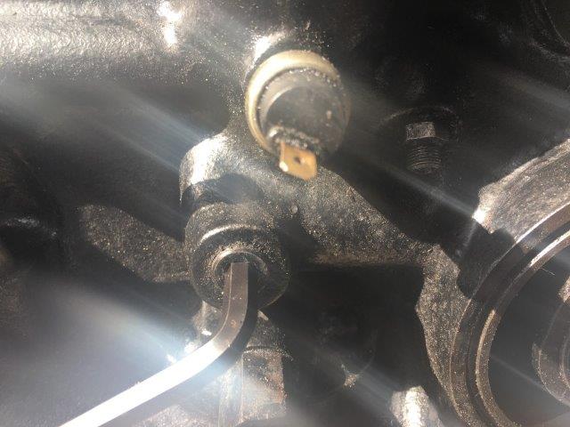
The pistons and con rods were dismantled. Before taking the crank out I checked the end float, see below, with the dial gauge and found it to be 0.009”, marginally over the recommended 0.006” – 0.008”. With the crank removed the bearing shells were found to be +0.010” on both the mains and big ends. The shells and the crank had only minor marking on them.
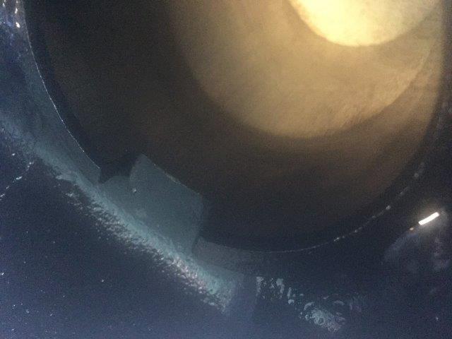
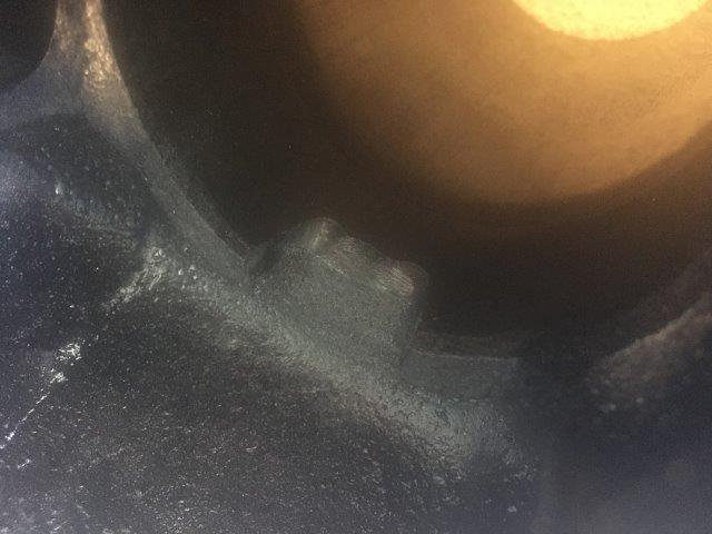
For the rebuild it was my intention to use new Maxspeeding steel con rods. There was a suspicion that the 52 year old original rods could have stretched and there was a special offer discount on the new steel rods, so I had them. The original rods are I section. The new steel rods are H section. I had been informed by my engine builder that there was a chance that these new rods would be wider than the old ones resulting potentially in interference with the cylinder skirt. A trial assembly of one rod proved this to be exactly correct, on both sides, i.e. on the downward stroke and upward stroke. I had to take a die grinder to each side of all 6 cylinders to create a chamfer approx. 5 x 5mm in the skirt to overcome this clash. See below, first photo before and second photo after grinding. Quite awkward to accomplish but absolutely necessary to avoid serious future damage.
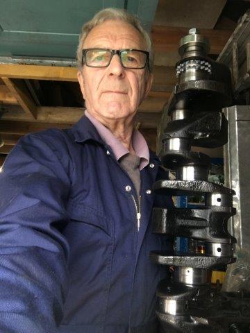
With this accomplished the crankshaft could finally be removed. See below. I’ve been informed by SWMBO that it shows 2 old cranks together! I’m not sure what she means!
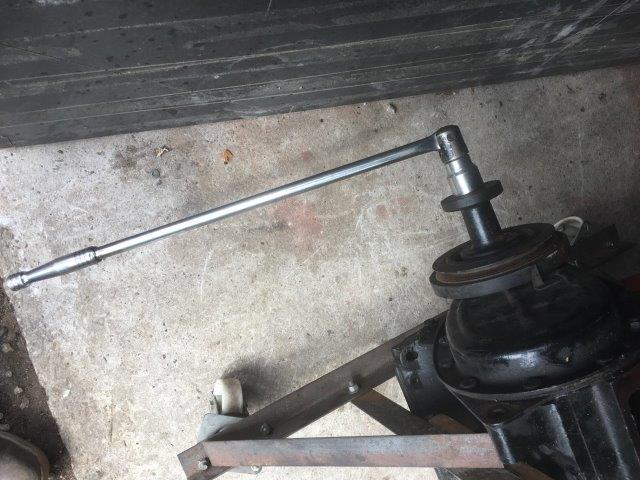
The cast iron oil pump bush below the distributor drive was the next thing to remove to allow complete cleaning of the oil gallery. A bit brittle and no longer available, this was removed a little tentatively. I’d been advised to drive it out carefully with a hammer and hardwood dowel or similar. Scared of breaking it I decided to draw it out with a threaded rod with a washer and nut underneath and large plate washer on top. This worked so far until the whole nut and rod assembly started to rotate and had to be finished with 2 pinch bars under the top plate. Success, phew.
With everything now stripped and cleaned up, the block, crank, etc. could go for reboring, regrinding, etc., etc. That was all delivered to the machine shop, Stanwood Engineering in Bawtry, South Yorkshire, on 22nd July 2020.
DMcD
28.12.20.