


JohnC
-
Content Count
920 -
Joined
-
Last visited
Content Type
Profiles
Forums
Calendar
Posts posted by JohnC
-
-
10 hours ago, RogerH said:
PS - I have tried to use semiconductor but they tend to be rather iffy in the car electric system - very noisy.
Mine is based on relays and cocks a snoot at rough electric.
I couldn't work out how to get the toggle on/off working with a momentary switch using relays. Please would you post your circuit? BTW a friend of mine has pointed out I could achieve the same using a tiny Arduino compatible processor. That might be my next project, although it wasn't available when the car was built. I wonder if it would better withstand the car environment?
John
-
10 hours ago, RobH said:
Yes - so really Q1 isn't needed because the power to the lamp is switched the same way. As I see it, when Q3 is off there is no power to the lamp anyway.
The voltage spike generated by a relay turning off can be quite big - up to hundreds of volts sometimes - and semiconductors can be damaged by it. A diode wired in parallel with the coil, oriented so it is reverse-biassed and does not conduct with the applied current, will short-circuit the spike and protect circuitry.
Aha! The penny drops. Thanks Rob - you're absolutely correct. I designed the circuit in bits and changed my approach a couple of times. Q1 was leftover from one of those changes. Didn't do any harm but completely unnecessary!
And I'll add a diode as you suggest. Updated schematic and Spice file attached.
Exactly the input I was looking for in posting this, even if I was a little slow on the uptake
")
John
-
Hi Rob,
Q1 only allows a current (through D1) if its base is energised by an emitter current from Q3, which in turn is only turned on when there's a high signal from the Q pin of the IC. The overdrive relay is represented in the circuit diagram by R10, and is also energised by the transistor Q3. The Vss pin is simply not earthed when the o/d interlock switches are open, and so the whole circuit is inert. Does that clarify things? I confess I'm not sure what back-emf spike will be generated.
Cheers,
John -
We're still in lockdown here in Sydney, and idle hands the Devils work do (as my old religion teacher told me many times). So I decided to design my own overdrive logic controller. I've always liked the intent of the logic controllers out there, but I prefer to brew my own. I also like to try to do so using components which were available when my car was manufactured. So here's my effort. I really would appreciate any suggestions for improvements (@Lebro - looking at you!).
My intent was this:
- Overdrive only available when inhibitor switches allow it (obviously)
- Overdrive is selected/deselected by a momentary switch.
- Overdrive is deselected whenever there's a gear change, and needs to be manually selected again afterwards if so desired.
- A warning light is illuminated when overdrive is selected.
- The overdrive warning light is dimmed when sidelights are on.
Here's the circuit I came up with. The CD4013 flip-flop IC was first available in 1968, and may well have cost as much as the TR6, but I think I've satisfied my intent to be "period". The circuit works in the LTSpice simulator, and on a breadboard in the car (including the warning light) but I haven't done the work to smallify it onto a soldered board. My next step is to get out the soldering iron, but I thought I'd seek critical input first. Attached is the schematic and the Spice file in case anyone wants to play with it.
Cheers,
John -
On 9/20/2021 at 6:28 PM, stuart said:
Thats from ill informed people who dont read the specs of the links I put up.
...and for ill-informed people who think 105psi is "high pressure". It ain't, in the world of hose manufacturers. Several thousand psi is more like it. But as you say, read the specs!
John
-
5 hours ago, Lebro said:
This dimmer circuit works for me
Me too (thanks Bob). Maybe obvious (wasn't to me) but you need to change all the bulbs to LED. If they're a mixture the dimmer will be less effective.
-
I'd be pretty impressed if hot dip galvanising could double the weight of a chassis! Particularly as it's less dense than steel. Very diligent operator, and worthy of promotion to management, his/her performance being so poor! Really, all? Hot dip galvanising is the gold standard. There may be poor practitioners but caveat emptor.
John
-
It's a thing of beauty! I wish I could justify it. I have occasionally (er, twice) lamented what a pain it is to change the cam timing. I think I would need a vernier cam thing and a new cam to justify the purchase. Where's my piggy bank?
John
-
On 9/5/2021 at 8:38 PM, RobH said:
If you look at the bulbs they are 'projector' style with all the light coming out of the front in a controlled beam.
The H4 replacements I got from classiccarleds have no forward-facing beam. All goes via the reflector. Maybe the H4 adapter Bob mentioned could be an option?
John
-
12 hours ago, Mike C said:
Any chance you could tell me the brand and model number.
These ones. Sorry, I didn't note the manufacturer details.
John
-
On 9/4/2021 at 7:34 PM, Roadrunner Paul said:
How does the mounting of the LED driver external to the headlight bowl work? Do you have to drill an extra hole in the bowl for an extension lead? Does the existing wiring into the bowl have to be removed, necessitating pulling out the bayonets from the front wiring loom? I've never seen an explanation of this!
I had to have a look at one of the headlights to refresh my memory! Anyway, it was pretty straightforward. The headlight LED unit itself is a direct swap for the H4 bulb. There's some adjustment available to get the orientation of the LEDs in synch with the lens, but I found the setup as supplied was fine.
There's a lead from the LED unit to the IC box, with a waterproof connector in the middle. The IC box itself I couldn't fit inside the headlamp bowl so I disconnected the lead, threaded it through the original hole and reconnected on the outside ( I don't remember having to open out the hole as Dave did, but I may have). I secured the IC box to the outside of the bowl using a cable tie (had to drill a couple of small holes for this). To get the original feeds out of the bowl I think I simply removed the female spades from the multi-connector block, pulled them out of the bowl, and put them back in the block. The IC box had a suitable set of male connectors in a block, if memory serves. No mod required to the loom, although I do have a slightly longer than necessary length of wiring in the wheel arch.
Hope this helps.
John
-
2 hours ago, Mike C said:
Have the LED headlights been passed during your annual pink slip Inspection? I'd be interested in fitting them if their illegality is a non event in practice.
Yes. In fact it was the inspector who pointed out the sidelight oddity. Having said that, he’s a very understanding inspector. YMMV. Probably more important is having them noted on your insurance policy. Which I haven’t yet done. D’oh!
John
-
Hi all,
I thought I'd share my experience of doing a comprehensive upgrade of my TR6's lights to LEDs. I replaced everything, with a couple of exceptions, noted below.1. Instrument lights: Straightforward replacement. I went for warm white, but that's a personal choice. I also have blue and red, just to see which I like best (currently trying blue). My panel dimmer has never been any use (who would want to dim the original lights from their all but imperceptible glow?) but I took the opportunity to replace it with a new one inspired by Bob "Lebro" here on the forum. Works a treat, and I may even need it, the new lights are so bright. A couple of observations: The original speedo and tacho have blue filters for the instrument lights. These were very cloudy on my car, so I removed them. Much brighter, and I can get the blue colour with blue LEDs if I like. Not sure about blue yet. The minor instrument gauges are painted pale blue inside. I repainted them white - noticeable improvement in brightness. Again, I can adjust the colour by using different bulbs.
2. Warning lights: I followed the advice of the suppliers and didn't replace the ignition warning light. I gather its resistance is important in waking up the alternator. I replaced the indicator repeater (see 4 below), but it's a bit dim. As if it needs a longer pulse to light up. Still, no worse than the original. The LED oil pressure warning light is great. Bright and impossible to miss. I did replace the high beam warning light but it was so bright (check at night!) that I went back to the original bulb. Appears sadly greenish in comparison to the blue panel lights I'm currently trying.
3. Headlights: Pretty straightforward, although there's a control box that I couldn't fit in the headlamp bowl. It's outside, secured with cable tie. A bit of a faff, but so worth it. I went for the modern bluish white, and I Can See ! Prior to the upgrade I had Osram Nightbreakers supplied via a fat cable and relays. Even so, huge improvement.
4. Indicators: Simple replacement all round, with the addition of a new relay as the original one doesn't work with the low resistance of LED bulbs. The amber LEDs are sooo much brighter. And I can hear the relay!
5. Reversing lights: Replaced with bright white. Reversing in the dark is no longer guesswork. Great.
6. Sidelights and number plate lights: Straight replacement. I went with warm white, and they are still noticeably brighter than original. Not sure the sidelights are up there with DRLs, but better than the original candles. BUT see 8 below.
7. Stop/Tail lights: What a difference, particularly with the stop lights. Really bright. Make sure you choose red LEDs rather than bright white as the colour spectrum of white LEDs will give you a pink colour through the red lenses. BUT see 8 below.
8. Even though all worked *almost* perfectly, I did experience two odd behaviours:
1. With all lights off and ignition on, pressing the brake pedal lit up the brake lights *and* the sidelights.
2. With side/tail lights on but ignition *off*, depressing the brake pedal turned the side/tail lights off. Brake lights did not illuminate (as they shouldn't).
Issue 1 was clearly that the stop lights were earthing back through the tail light circuit to the side lights. I investigated earthing, even running a nice thick cable direct from the lights to the battery, but to no avail. To fix the problem I needed to insert a diode upstream of the tail light supply. Issue 2 was solved with a diode upstream of the stop light supply. I am sure YMMV, but this may save you some head-scratching.
9. I have subsequently replaced the reversing lights with dual filament (?) white/red LEDs (which needed new bulb holders intended for stop/tail lights). The red colour is connected in parallel with the stop lights, giving an additional (very bright) stop light. By inserting a diode into the stop light supply to this filament, I'm able to use it as a high-intensity rear light (supplied from a switch under the dash). I'm becoming a dab hand at soldering up a fragile diode into a sort-of robust bit of wiring!I'm really happy with the result. I have headlights that work, I can read the instruments without my passenger holding a torch, and I'm (more) confident that other drivers will see my indicators and brake lights in daylight. In addition, I have high-intensity rear lights, and I can hear the indicators.
I was disappointed that the dual "filament" LEDs didn't have protection against the odd behaviour. Perhaps subsequent iterations will do.
I used bulbs from classiccarleds.co.uk and bettercarlighting.co.uk. Both were helpful with after-sales support. Gil at bettercarlighting explained why I was seeing the oddness with the new stop/tail lights.
Hope this helps you if you're considering an LED upgrade.
Cheers,
John
-
Depending on what you want to end up with, it may be worth considering a Quaife LSD. Made a huge difference to my 6 in the wet. But pricey, particularly after paying for the machining to make it fit. It's not quite plug'n'play. If you look carefully at the small print it's only intended for earlier cars without IRS, in spite of being listed for the TR6...
John
-
On 8/23/2021 at 3:54 AM, Keith Warren said:
Second photo
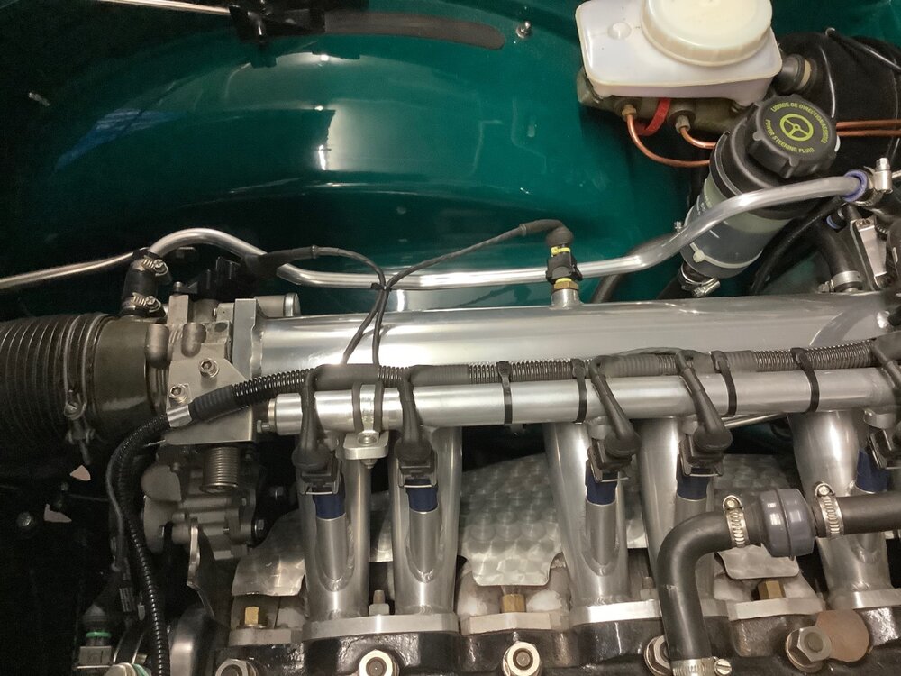
Goodness! If I fit a similar venting arrangement will my engine bay look like that? Super impressed
-
Thanks Steve!
-
I was amazed and delighted how many rattles disappeared when I overhauled the entire suspension. New bushes all round. They happened to be Superpro, in the standard spec (blue?), and I'm sure it was a simply replacing the completely worn-out ones that brought the transformation. Don't assume you have what the manufacturer intended, and therefore need an upgrade. You may have woefully less than the manufacturer intended, and need...maintenance.
John
-
2 hours ago, Bahman said:
Any other advice is welcome...
If there's one thing I've learned in over 30 years of TR ownership (yes, I know I'm a newbie), it's that you need to sort the simple (and cheap) stuff first.
John
-
6 hours ago, Bahman said:
My car has a points-ignition....so must be inside the coil...
As Rob says, it's in the distributor, not in the coil. It's a seperate item. Easy to identify if you take off the dizzy cap. And why not change the points and condenser while you're there? The blue thing does indeed look like a noise suppression capacitor. Nothing to see there.
John
-
On 8/17/2021 at 7:08 AM, Ronald Morris said:
what is PI ?
PI = Lucas Mk II Petrol Injection. Irrelevant in your case as your car has carburettors. Adds a whole new dimension to the joys and sorrows of a car so equipped (they weren't sold in USA). I love it. Others, not so much. Some ( @Tom FremontI'm looking at you!) say Webers are the only way to get fuel into a TR 6 cylinder. May they live long enough to see the errors of their ways

Cheers,
John -
On the subject of fuel smell, I don't know if the TR5 has a similar problem to the TR6, but on the '6 any non-standard exhausts (e.g. "wheelbarrow) can cause petrol smells. May be caused by the flat tail on the '6, but worth thinking about if you have a sports exhaust.
John
-
Thanks Rob. Lockdown clearly feeds idle and frivolous thoughts
. Thanks for the explanation of the circuit. I was aware that LED bulbs have more in them than just several LEDs, but I hadn't appreciated that the circuit was for just an LED alone. Should I delete the image in case somebody as ignorant as I am tries to be clever?
I've now installed a pot exactly as per Bob's design (thanks @Lebro). I did run into one wrinkle though. I have a seperate vacuum gauge which has an incandescent 2.2W bulb (65Ω I think). That's enough to upset the balance. Instead of the lights going out just before full travel on the pot, they go out at about 50%. As the vacuum gauge is part of an auxiliary binnacle in top of the dash (mounted in the ashtray hole), I've decided to live with it. I don't leave the binnacle in place all the time, only when tuning (it also has an AFR gauge and knock sensor) so not a big deal. If I wanted to be really anal, I'd source a MES bulb holder and fit an LED bulb. But the LED in the knock sensor is so bright that it would make no difference to glare at night!
I do love tinkering
John
-
Fair enough. TBH for me, the reduction in current was a beneficial side effect of switching to LEDs. The primary reason was that I wanted decent dash lighting! I'm now tinkering just because I can
I have no idea how an LED bulb is wired internally, so I don't know how the circuit above would work. I'm just curious whether there's a clever way to use the original rheostat by adding external mods.
In any case, you're correct that one can't use the original rheostat in Bob's circuit. It's a simple variable resistor, whereas Bob has wired the pot as a variable voltage divider. The original only has a terminal on one end of the resistor wire - the other end floats. FWIW the rheostat in my car (1971 TR6) has a resistance varying from 0.6-5.6Ω. Probably 5Ω with some age.
John
-
Thanks @Lebro. So the holes reference is irrelevant to my TR6. Phew.
In my idle googling, I came across the circuit in the attached image (it came from this thread). I was never any good at electrickery (although your circuit has triggered vague memories of messing with Wheatstone Bridges at school), but it looks like it could be adapted to use the original dimmer by using a suitably rated resistor. Is that right, or am I missing something obvious?
Cheers,
John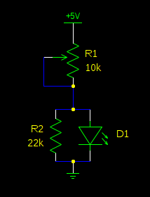

TR4 -6 Door Hinges
in General TR Technical
Posted
FWIW I refurbished a couple using roll pins after drilling out the hinges to suit. Drilled the centre very slightly larger than the outers. Easy, quick and cheap. Only issue was that a couple of hinges I tried to fix refused to cooperate - I couldn't get the pins out. Both the pins and hinges were worn btw. Six years later and all is still fine.
Thanks to Richard Crawley for the idea. I think I have a note somewhere of all the relevant drill & roll pin sizes that I used if you need more info.
Cheers,
John