

RobH
-
Content Count
8,983 -
Joined
-
Last visited
Content Type
Profiles
Forums
Calendar
Posts posted by RobH
-
-
It sounds as though the auto-parking contact in the motor is 'made' to earth all the time Alan. ( Power to the motor should not come through the voltage stabiliser - that is used just as a convenient connection point for switched-live on the power connection to the stabiliser - B terminal. The same point also feeds the heater fan and indicators )
The DR3A usually has connection to the self-park switch by the red wire running on the top of the gear housing. If yours is like this make sure that the connection to the tag isn't also touching the metal body and that it isn't earthing where it exits the motor body.
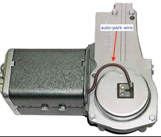
If you can disconnect the wire from the tag, does the motor stop? If so there is a problem with the internal switching.
This is the contact. The brass plate gets power from the red wire and there is an earth 'wiper' contact on the gear. The motor will run until the wiper gets to the gap when power is cut off. If the wiper is bent it could be earthing the plate all the time.
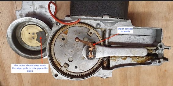
If all of this is OK perhaps there is a short to earth inside the motor itself.
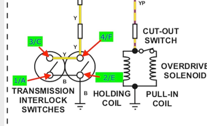
There is another rarer form of the motor with a switch like this :
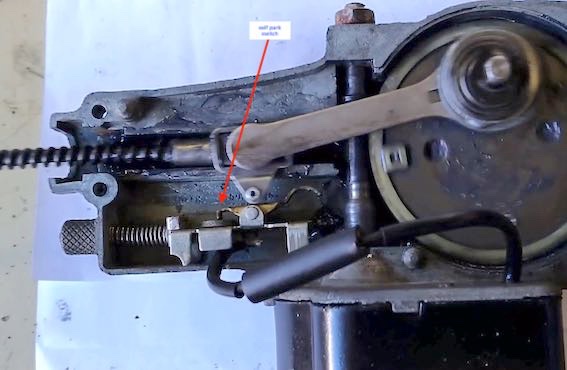
Again, if the link wire is shorting to earth, or the switch is bent, the motor will run continuously.
The two-speed loom and switch connects earth first to the brown/green wire for fast speed and then to both brown green and red/green together for slow speed so connecting a single-speed motor to brown/green will turn it on for the first switch position. If it was connected to red/green it will turn on in the second switch position.
-
1 hour ago, NC-TR4 said:
just top up to filler plug level as the Triumph workshop manual describes
Yes unless you want to change the lot - in which case do it off the car because you have to exercise the lever arm to get rid of air.
-
The system doesn't 'need' an overflow bottle or another header. It is designed to have air in the top of the radiator and filler neck which.contains any expansion. There should be no overflow if the radiator isn't over-filled. There really is no benefit from using it full with an external catch bottle but that is how later cars were arranged and some people feel happier with it that way - perhaps because it is a more familiar arrangement.
-
46 minutes ago, Tom B said:
The “proper” way to dim an LED is to switch it on and off very quickly. This is completely standard practice. The technique is called Pulse Width Modulation (PWM).
PWM is one way to do it if the LED lamp is a simple one with no internal brightness- control chip but is by no means the only way. Current control is just as 'proper' since luminous intensity is almost linear with current. A series resistor is considerably cheaper than a PWM controller. (I would agree with Bob that using a 10Amp PWM unit on LEDs drawing a few mA is certainly overkill
 )
)
PWM has its own drawbacks. The fact an LED has instantaneous response means there can be problems with 'strobing' of moving objects if the PWM frequency is too low. Sometimes this is noticeable when you just move your eyes - things can momentarily appear to flicker. (I was in a restaurant not long ago where the tables were lit by dimmed LED spotlamps. As people moved cutlery while eating, the LED lighting gave a most disconcerting flicker effect from the reflections. If the lamps had been old-fashioned halogen you wouldn't have seen it because of the thermal lag in the filaments. )
-
This old thread has some photos that might help:
-
Yes it's the same for me John.
-
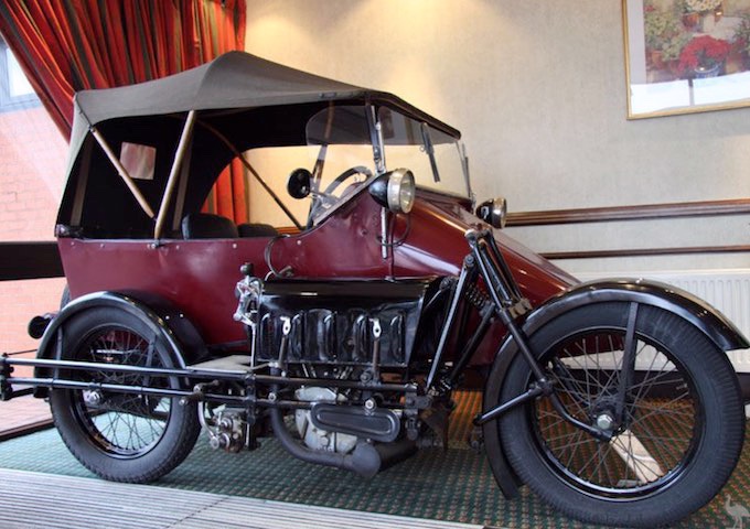
Not sure whether this qualifies for the thread. Its a Seal bike which is driven from the side-car.
-
2 hours ago, AJAS said:
1 small wire connected – brown (not much visible so could be brown / red?) spliced to an extended wire and connector, live with ign switched off or on!
Did you measure that with the wire disconnected from the alternator?
I'm getting a bit doubtful about all this as there is a chance for something to go very wrong and cause damage or even a fire unless you are careful as there is no fuse in the battery connection to the alternator. If what you say is correct and the ignition lamp really was working before, then whoever installed the alternator must have fiddled with the wiring in a non-standard way so the colours on the small connection are not right.
If that thin wire is really live all the time it may be part of the original wiring as the old alternators did have a live feed from a four-way junction point (which I think is on the wing) but why was the wire cut and then extended? Did he cut both wires by mistake and then maybe extend the wrong one? If so the ignition light could not have worked afterwards.
You say the ignition switch has been replaced recently - did you do that yourself? Were the wire colours on the switch as per the diagrams?
Does the bulb-holder for the ignition lamp have one white wire and one brown/yellow one? If so does the brown/yellow wire go to the 'snipped' wire or to the extended one?
-

You don't need to photograph them - you can download them already in PNG or JPG format like the one above.
https://www.freepngimg.com/png/85280-emoticon-emotion-samsung-iphone-galaxy-emoji
-
Ah - OK. That is a Lucas ACR pattern alternator.
The continuity tests you are doing are finding return paths through equipment in the car which is why it looks as though the positive lead goes to earth. It is not a meaningful reading.
You say the reversing light works - which is an indication that the battery is OK but more than that depends on where it is connected and whether it is switched by the ignition switch. The fact the oil light comes on with the ignition shows there is power to the switch and that the switch is working. It should also feed power to the ignition light, which earths via the alternator, and also to the indicators so they should work too. If they do we need to look at the alternator end of things.
There is a thin wire connected to the alternator - probably the one on the right in your photo. It ought to be brown/yellow but since alterations have been made to your car that may no longer be the case. That wire is the other end of the ignition lamp and if you disconnect it from the alternator and connect it to earth, the lamp should come on when you switch the ignition. That would prove that part of the circuit is ok.
Are you sure the engine is properly earthed to the chassis by a heavy braid ?
-
1 minute ago, dpb said:
Put the motor back though, and it is impossible to move the cog.
That's because it is a worm drive. You can't drive them backwards.
-
I take it this is a single-speed DR3 motor. The high current is probably due to the motor being 'stalled' - as it runs it develops a back-emf which reduces the current but without that there is only the DC resistance of the armature winding.
If not mechanically stuck, it could be that the field winding is disconnected in some way. The armature will still pull a high current but the motor will not rotate. You could check that by lifting one of the brushes - the high current should drop but there should still be a small current taken by the field. If there is no current the field is open circuit
-
It isn't exactly clear to me what you are doing with these 'continuity' tests nor why you are doing them. Depending on what you are using to do the measurement you may get all sorts of weird results, because everything is connected to everything else in some way and an over- sensitive meter can show connection where the path is rather tenuous.
The best instrument for electrical fault-finding on a car is a small 12v bulb with wires attached.
You say there is 'no switching from the relay' - what relay is that? Do you mean the starter solenoid?
It's also not clear what type of alternator you have - 'three-terminal jobbie' could be anything. Is it a Lucas or a Denso type? If you are not sure a photo would help.
Did you try anything other than reversing lights? Do the horns, indicators or headlights work ?
-
Welcome to the forums Shaun. No doubt someone will be along soon with an up-to-date answer but in the mean time there have been several discussions about this colour in the past as a forum search will show, e.g. : -
(click on the arrow top right to see it)
-

Wish I was that energetic !
-
It's a bit late now to point out that you should have labelled them before you disconnected Richard ! Black is earth, green is probably the indicator lamp and red is the side-light.
I expect red goes to red and green goes to green/white at the connectors near the RH horn.
-
It is counter-intuitive but there is really no danger from electrics being inside the petrol tank as long as here is liquid petrol in there too.
I have posted this before:
Liquid petrol itself does not burn so although it sounds completely wrong, immersing electrics in petrol is really quite safe. it's the vapour that is flammable but that is only over a very restricted range of fuel/air mixes - 1.4 to 7.6 % petrol to air by volume or thereabouts. Usually the vapour concentration in the tank is very much greater than that so there is no risk of fire from the sender. The partial pressure of petrol is about 4.5psi under normal ambient conditions so as long as there is liquid petrol in the tank, as an approximation there will be around 30% vapour by volume which is too rich to burn.
Petrol vapour is heavier than air, so air will not readily enter the tank to dilute the mix even when the cap is off. (That does mean the risk increases greatly if the tank is completely empty of course as the vapour then becomes more dilute, which is why one should be very wary of repairing tanks using hot methods, or inserting any potential ignition source into an 'empty' tank . The risk is higher also in vapour displaced from the tank when filling it, as that may well come within the flammability range when it meets the open air )
-
...or a UK source :
-
It's tight Rob. Depends on how much clearance you have between the bell-housing and the bulkhead. I could just get a reversed thin spanner in there on my car and move the nut one flat at a time, but yours may be different. I think some people even resort to making an access hole in the transmission tunnel which allows a socket with long extension to fit- perhaps your car already has one since the PO must have fitted the starter in the first place?
When replacing the motor on some you can reverse the front plate, so the stud is at the bottom.
-
1 minute ago, john.r.davies said:
we have a Snark!
As long as it isn't actually a Boojum.

-
Powerlite so probably an RAC 102.
https://www.powerlite-units.com/high-torque-starter-motors.html
The cylindrical thing on the top is another solenoid, which throws the pinion into gear and at full travel 'makes' an internal high-current contact to power the starter itself.
There have been instances of the internal contacts failing, the pinion getting damaged and the external link wire failing. I believe Powerlite are good at providing spares and support.
edit - Snap!
-
Excellent news Mick.
-
-
3 minutes ago, james christie said:
Surely an easy test is to short circuit the terminals with a heavy screwdriver?
An easy test indeed but one fraught with danger James. There is a lot of earthed metalwork near those terminals and one slip with the screwdriver could easily short the battery. There is no fuse protecting things, so a resulting arc could do an awful lot of damage.
Not worth the risk in my opinion.
Wiper motor continually on
in TR4/4A Forum
Posted
This is what is inside, Alan - though in your case the wire to the switch is green/brown. With no connection to terminal 1 the motor can run continuously if there is an earth getting to the left hand motor brush (LH as drawn that is), so that includes the motor terminal, the link wire, the parking switch and any wires in between.