

RobH
-
Content Count
9,092 -
Joined
-
Last visited
Content Type
Profiles
Forums
Calendar
Posts posted by RobH
-
-
Soldering does not weaken the wire if done properly Iain. If anything the insulated crimp-on connectors are the ones with poor strain-relief in my opinion, particularly if the rear crimp is done badly. Using solder type Lucar connectors you should use just the forward lugs for the bare wire, make the joint first and leave it to cool, then bend the wire-support lugs around the insulation to properly support the joint and wire.
Rob
-
The ignition lamp staying on does not indicate a low battery - in fact it shows just the opposite. The light should go out when the generator voltage is higher than the battery voltage, so if it stays on it shows the generator isn't working. What does the ammeter show when you run the engine?
What the fault could be depends on whether you have an alternator or a dynamo. The test Dick suggests above will not work if you have an alternator - without a good excitation current from the ignition lamp the alternator will not start to generate (as people have found out when they try to replace the bulb with an LED)
Rob
-
+1 for what Kutscher says Alex - its a peculiarity of the breed that if the rad is filled to the top they will always throw out water when hot. There should be only a few mm of water visible at the bottom of the filler neck. Its worth trying that and seeing what happens before doing anything else.
The temperature gauge should have stabilised within two or three miles though - it should not take ten as implied in your first post (but perhaps I am reading that wrong). If the rise in temperature really was very slow it might indicate the thermostat is not working properly, i.e. stuck open. The normal characteristic on my car is a rise to around mid way on the gauge (185 F) after a mile or two then as the thermostat opens the temperature drops slightly before rising back and stabilising again.
Rob
-
Jim - a set-screw is a headed fastener similar to a bolt and is threaded all the way to the head. (A bolt is threaded only part of the way up and has a plain section below the head). Your double-threaded studs would never be described as set-screws.
Rob
-
Items 2 and 3 on this diagram:-
The double-ended studs you have are probably mostly for the manifolds, though there is one in the centre of the timing cover.
Rob
-
Thats very nice. Looks like a cross between a Jacobs chuck and an ER collet. Does the rubber interleave give a wider range of adjustment than available from a spring collet? You are certainly right about the boring bar, and it takes several passes of cut for all the flex to be released I find, even with a fairly robust one.
-
Red light (say 700nM) is about 2.76 x 10^-5 inches wavelength or 0.0000276 inches so yes, one tenth of a thou is about four wavelengths. Your lathe skills are impressive Alan. The cross-slide leadscrew and the bed on my Drummond are so worn that to cut consistently to one thou is impressive to me !
Rob
-
Could it be warped brake discs Nigel ? You could check that with a dial gauge without needing to strip anything.
Rob
-
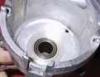
On the face of it you would expect that bush to have a pretty easy life. Should be little sideways force on it other than the CB spring unless something odd has happened with the centrifugal weights.
-
Is brass the right material for this bush Roger? Brass is not a great bearing material. Surely its more usual to use bronze or a sintered material.
This pic seems to show a silvery material which doesn't look like brass to me.
Rob
-
The original type bimetallic flasher needs the right current to operate because it relies on a heating element. Putting LED bulbs in means there isn't enough heating of the strip to make it switch. If you are going to retain the LEDs you need a compatible electronic flasher unit.
Rob
-
On your original flasher unit the 'X' is the power input, P goes to the warning lamp and L to the flashers switch. The new units are different as you say and do not have a separate connection for the warning lamp. They are wired up as 49 power in, 49a to flasher switch and 31 to earth. You can't use those without making wiring changes because there is no connection for the warning lamp.
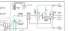
What seems odd is that according to published schematics, the TR250 has a two-pin indicator-flasher unit (below). The three-pin one is the hazard-flasher. Are you sure you are looking at the right one?
Rob

-
There might be another solution I believe. I have heard of a firm which can supply in-line gearboxes for the drive cable.
http://www.speedograph-richfield.com/html/minature_gearbox.html
Rob
-
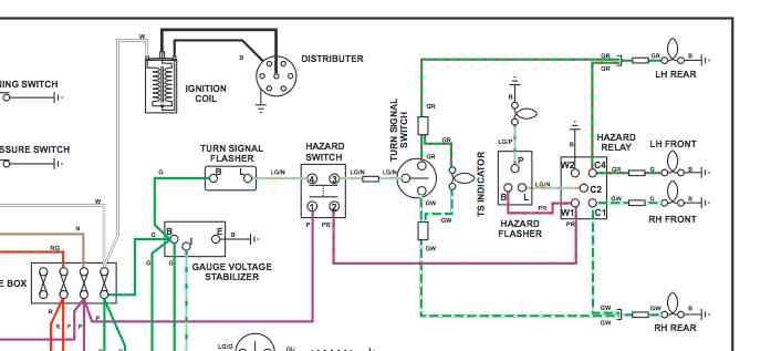
If its not something like LED bulb then there must have been some changes in the wiring - perhaps wires put back wrongly after disconnection. To start diagnosis you need to find out whether its the turn signal flasher or the hazard flasher which is operating. Relevant bit of the schematic below.
Rob
-
I believe the two pumps operate differently Richard, though the result is the same if you get the same flow rate and pressure spec. The 'electronic' cube type runs all the time and is a pusher pump which should be mounted near the tank. The cylindrical type is an interrupter pump, like an old SU pump which only runs when needed when the carb float valve opens and outlet pressure drops. It can be used as a pusher or suction pump so can be mounted in the engine bay.
An alternative to these is the Huco which is also an interrupter and suction type for engine-bay mounting. If you get the right low-pressure-rated pump so that the carb float valve can cope, you should not really need a fuel pressure regulator.
http://www.fastroadcars.co.uk/shop/index.php?act=viewProd&productId=29
Rob
-
Conventional wisdom seems to be that the engine design of older cars requires a level of Zinc compound additive (ZDDP) which is not met in oils designed for modern cars. That is nothing to do with the synthetic or semi-synthetic make-up. Some posts on earlier threads too have indicated problems with modern oil which is too thin for the clearances in older engines and the higher levels of detergent can move old carbon build-up which is best left in place. In the short term there will not be any dire consequence but personally I would change it for the 'proper' stuff as soon as convenient.
Here is a link to some relevant gen from Castrol, though of course pointing to their own product:
http://www.castrol.com/en_gb/united-kingdom/products/cars/classic-oils/classic-engine-oils.html
Rob
-
Try mail(at)kdib.co.uk
-
Apologies for the late post on this topic but Paul in post 31 has the answer, I feel. My 3A used to do just this and yes, just pull a bit (a lot) harder on the choke knob and it comes out another inch - bingo - starts with no problem. First choke one inch out easy pull, full choke two inches out two-hands pull. Looking at the run of the cable it is very close to the heater and does quite a sharp bend at that point; just where the flexible part of the cable meets the rigid guide of the choke knob assembly. Enough to make it very sticky given that the inner is a solid wire instead of a braided cable.
Rob
-
I too am an electronics/electrical professional Alan - and I look on it the other way. Each to his own I guess and it won't hurt to fit such a device, but I still think any damage will be done long before the protection operates, given that failure in a component is more likely than a short in the wiring. Does the blurb you mention show the current/time curves for the fuse?
I have found what I think is the type here:
and the opening times quoted have quite wide tolerance.
Incidentally while I understand your meter isn't a cheap Chinese special, I still doubt whether it is calibrated for the type of current you are trying to measure - normally they are calibrated with clean DC for those ranges and can give errors on anything noisy as I said. Probably not big errors, but there nontheless. (AC ranges are different of course as that will probably be true-rms if its a good meter) I have come across too many people -even professionals- who will believe a digital readout to be correct to the last digit.
Rob
-
Alan - why do you feel it necessary to 'protect' the starter circuit? Its really a complete waste of time since it takes about ten times the rated current to blow a fuse quickly enough to save the wiring, and if something is pulling that sort of current its not worth saving. Fuses do not blow at the current written on them - a 100 amp fuse to BS88 will take about 100 seconds to blow at 250 amps. A 200 amp fuse will probably need about 500A to blow in the same time, by which time your wiring will be well alight and the battery knackered. If you put a smaller fuse in so that it will afford some protection then the voltage drop due to its resistance might slow the starter.
Incidentally - digital meters can lie, particularly the clamp-on type as they rely on a good magnetic circuit in the clamp for accuracy. Also the position of the conductor in the loop can affect the reading. A DC type will have been adjusted to read correctly for a pure DC current - not one with noise and fluctuating current as you will get with a motor. You should not necessarily believe what it says just because its digital, unless it has been calibrated.
Rob
-
Same here Tim - though I used the similar Penrite Steering Box Lube which also comes in a 1 litre bottle. Its important to put oil in the steering column hole as well though, because that lubricates the upper bearing. I use EP90 oil for that as it has to be thin enough to run down the tube.
Rob
-
Yes Steve, the stator tube is within the steering column and clamped at the bottom with the olive and brass nut. You can certainly pull the wires out without removing the tube or undoing the olive provided you arrange the bullet connectors behind one another so that the cableform is thin enough, and keep them arranged that way using sticky tape.
Perhaps some people have been unable to do that because the wires have become stuck in the tube for some reason but since yours appear to be free you should have no problem.
As Peter says above, putting it back may be a little more complicated...
Rob
-
Steve - as you say it does sound as though the head itself is faulty. Its not something I have ever attemped but a repair is possible. The link below should get you to a previous topic about this and reply no. 20 has a link to a useful 'how to do it' document.
Rob
-
Steve, could it be that the grub screws have loosened and the disk it holds has rotated a bit? The odd feel could just be because the self-cancelling cam is now in the wrong place in relation to the switch mechanism. You still have to withdraw the head to get at it to re-align though.
If you disconect the cables there might be enough slack in the wires as they exit the steering box to withdraw the head sufficiently to have a look, without pulling them right back through the stator tube. Safest to tie a pull-cord on them though just in case as Richard says. (I seem to recall you only need to undo the olive if you want to take the stator tube right out ? Granted its a while since I did this). The indicator head is attached to a short length of stator which is a push-fit in the main tube and so holds the switch mechanism to prevent it rotating with the wheel.
To re-align you set the wheel straight ahead, undo the grub screws and remove the head. Then turn the disc relative to the head until it is central and self cancels equally both ways. Push the head back without moving the disc, ensuring the tube goes back into the stator. That might be a two-man job as you need to pull on the wires as they go back down the tube. Finally tighten the grub screws to clamp the disc in place. Easier said than done I guess and it took me a couple of goes to get it aligned right.
Rob


Radiator filler cap - Oil filler cap (MAYO)
in TR2/3/3A/3B Forum
Posted
Sounds like you have the wrong radiator cap John. The sidescreen TR cap should have a longer spring than most as the seat is further down the filler neck. Its probably not related to the oil filler mayonnaise which is due to not getting the engine hot enough for long enough to boil out the condensation. Too many short runs which don't get the engine thorougly hot - take the car out for some long thrashes this summer which should get rid of it.
Rob