

RobH
-
Content Count
8,954 -
Joined
-
Last visited
Content Type
Profiles
Forums
Calendar
Posts posted by RobH
-
-
59 minutes ago, Ralph Whitaker said:
Clock?, or memory to a radio.
Decadence ! This is a sidescreen car
 . A period radio would be manually-tuned and any clock would be wind-up.
Seriously, if you leave something like that connected you haven't really isolated all the electrics, so it depends on what you are trying to achieve. If there is a radio which needs continuous power you can't put the battery switch in the earth lead because the radio probably earths through its mounting bracket.
-
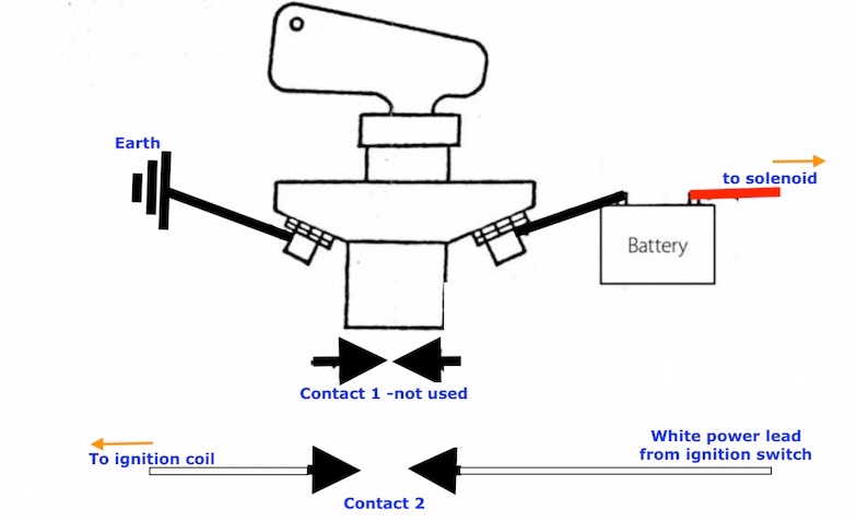
The switch has two separate functions. The heavy connections are to isolate the battery from the electrical system, but that won't stop the engine if it is running since the alternator will continue to supply power to the car, and if that is the case it will also be powering any electrical short that might have occurred. The smaller contacts are intended to be wired into the ignition system so that switching off also removes power from that circuit so stopping the engine and any output from the alternator.
The contacts labelled '1' are closed with the switch off and open with it on. The contacts labelled '2' are open with the switch off and closed with it on.
Most of the manufacturer's fitting instructions show the main switch wired in the live lead from the battery to the solenoid. That scheme is not entirely safe because if some metal item comes in to contact with the battery live terminal or wiring before the switch, and also touches the bodywork (or if in the event of a crash some deranged bodywork touches that terminal), there will be a short circuit. The better scheme is as Charlie says, to put the switch in the battery earth connection. That is safer because when the switch is off the battery is then 'floating' so that earthing either terminal to the body cannot cause a short circuit.
Auxilliary switch '2' can be wired in series with the supply to the ignition coil so that power is cut with the switch off. The easiest point to do that is probably in the power wire to the coil itself.
Contacts '1' can be used to earth out the supply via a high-power resistor but that isn't really necessary except for alternators having a battery-sense connection, where removing the connection suddenly can damage the alternator from a voltage spike. Lucas ACR alternators do not need this.
-
23 minutes ago, Richardtr3a said:
Is it better to buy a Durite or just the other one here on the forum ? Durite may be better quality.
I doubt there is anything much between the two Richard. Both Durite and Ripca/Ripault are reputable.
-
This is a bit of a 'can-of-worms'. The coil has one end of the primary winding connected to the HT winding and is meant to operate with that connection point going to the distributor. That increases the output voltage by a few hundred volts because when the points open, the windings are in series so back-emf in the primary adds to that of the secondary. By swapping the connections of the coil over, you lose that small boost because the connection point is held at 12v above earth.
What this means is that in correcting things to get the right spark polarity , you alter the operation of the system slightly. It's a bit academic and probably won't be noticed in practice - but then neither will having spark polarity the 'wrong' way round. Either way, the system isn't working in quite the way intended.
if you are going to the lengths of installing an alternator and changing the polarity, the right thing to do is go the whole hog and fit a negative-earth coil.
-
I understand that this is due to the cursory way the survey is often done these days- basically just a tick-the-box form from a quick visual, sometimes even just from photos rather than a physical check. The person doing the survey is paid by the insurance company and time is money.
You don't have to accept what the insurance company says and can challenge the assessment but you would need to hire your own engineer to do another survey and prepare a report. I'm not sure how that would work if you don't actually own the car though.
-
2 hours ago, Ralph Whitaker said:
you need to reverse the battery connections if you are not already Neg earth. Also radio if fitted will be affected .
Another thing you will need to change if you are swapping polarity is the instrument voltage stabiliser if that is a modern electronic type rather than the original bimetallic.
1 hour ago, chastr4a said:Any predictions on what might go wrong if regulator wiring was not changed over?
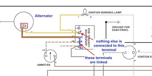
You can get away with not changing the wiring on the control box as long as you just insulate the dynamo ends of the dynamo leads and take off the earth connection from E on the control box. The box can't then do anything even though it remains connected.
You would need to connect the alternator field wire to D so it picks up the ignition lamp connection and find a way of connecting the alternator output to A or A1. Problem there is the remaining unused tags on those terminals are the smaller type and are not big enough to carry the alternator current so it would be necessary to make up some form of 2-into-1 spade adaptor.
-
This is one way to do it using the RB106 as a junction box with its internals removed and the three large spade terminals A1, A and D connected together with a heavy gauge link wire under the base. There is no connection to E. F is used just as a junction point. (Note that the D and F terminals are shown in the wrong order, for clarity in the drawing )
-
To be honest that looks more of a crack than anything. The ends don't look melted. There is blackening at the LH end of that link though.
-
All the best Waldi.
-
MHR Bob.
-
The choke mechanism certainly shouldn't be wet with fuel - and neither should the vacuum advance pipe. These are possibly signs of the jet overflowing due to too high a fuel level in the float chamber. If the mixture is way too rich the engine won't fire.
-
If you couldn't see any fuel in the jet it might be a clue as to why the engine stops Nick. Perhaps it has used up all that was there? You can usually see the glint of the liquid if you shine a torch down the hole.
The float chamber might be full but if fuel isn't getting through to the jet properly, it can't run. After all, that is the thing you have been working on and sudden onset of a new fault afterwards might be a pointer to all not being well.........?.
-
Two things David. The fuse should go as close as is reasonable to the power pick-off point and the starter solenoid is a good place only if you have no ammeter. If you do have one, it will register the lighting current as a 'charge' which is incorrect, so in that case the pick-off should be directly where the alternator output cable connects.
A 15 Amp fuse is fine - a fuse should be rated slightly lower than the cable it is protecting, though in this case since the lights draw a lot less current you could go even lower if you wanted.
-
That mod is only to reduce voltage drop on the switch Keith - it adds no protection whatever to the existing wires. Relays in the main lamp supply won't help you if the wires before the relay coils short to earth anywhere. There may be less current flowing there when all is OK but a short circuit to earth will still pull all the current it can through those wires. Only a fuse can save the loom .
-
29 minutes ago, Richardtr3a said:
Thanks Ralph what relay am I looking for ?
A Durite 0-727-12 is the modern type
or a part number 140201 here:
https://www.autoelectricsupplies.co.uk/p/12-volt-relay-make-and-break
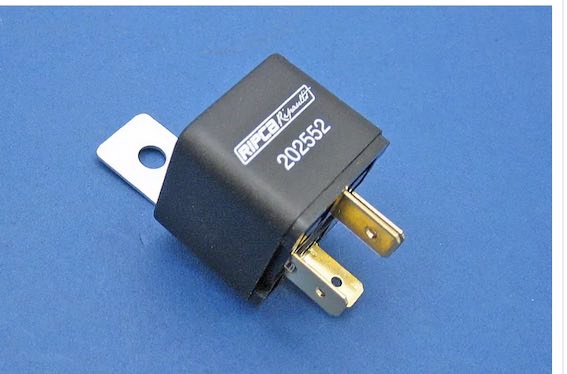
If you go to a local shop ask for a "4-terminal 30amp make-break relay"
For modern relays the connection terminals are numbered rather than letters and the equivalents to the original are:
C1=30. (brown/white wire), C2=87 (yellow/purple), W1=86 (white), W2= 85 (yellow/green)
-
You seem unsure whether the battery is being charged - what does the ammeter show?
As Bob says, 12v should be present on 'A' all the time If it isn't it's likely the heavy-current loop inside the ammeter has become detached.
-
I guess this is for an early car with ammeter - are you looking to replace the wires?
The larger wire which goes to the ammeter carries the peak battery charging current which can be 30A or more. A suitable wire for that would be 84/0.3 rated at 42A, to give some margin.
The smaller wire basically just carries the horn current which peaks around 10A and the hazard flashers at 7A plus maybe a few other things if the car is a US model. A suitable wire size is 44/.30 (27.5A rating).
-
The rattle could just be that the gearstick anti-rattle plunger isn't there Richard, as others have said. The name is the clue.
If the OD relay clicks only when the gearbox is in gear, the two interlock switches are working as they should.
This is a direct UK-source replacement relay:
https://www.ebay.co.uk/itm/164379224543
At that price it's worth making sure you really need one !
-
Have you removed the carb piston chamber and looked at the fuel level in the jet Nick? That's the important thing. It should be a short way down from the top (not critical - 1/8 to 1/4 inch is fine).
The wetness you describe sounds like it could be overflow from too high a level. The starting problem you describe could be a grossly (!) over-rich mixture due to that.
-
It sound as though you may be emptying the float chambers more quickly than they can replenish, though 5-10 seconds is pretty short for that so perhaps just emptying the jet tube . Are you sure there is good flow from the float chamber to the jet, through the bits you have replaced? Have some particles of that old ptfe tape caused a blockage?
-
-
If the ones you have are genuine Lucas they ought to be OK Mark as long as no-one has been fiddling with them. The aftermarket repro ones have a bit of a bad name as some are made from shoddy materials and wear out quickly.
It's a toss-up whether its worth getting old Lucas ones refurbished though as the decent electronic ones are fine and probably cost less. As another option you can buy just the electronic modules (DVR3) to fit in the cases you have:
http://dynamoregulator.com/products.html
-
There isn't much detail in that ad but I think that is a standard electro-mechanical regulator which has had a power transistor fitted to do the switching as a modification, to overcome burning of the mechanical contacts. It is not a full-blown electronic regulator.
It doesn't say whether it is a genuine Lucas item or an aftermarket one - probably the latter in which case it's a bit of an unknown quantity. Its is certainly cheaper than an electronic conversion though like these which are known to be OK:
https://www.dynamoregulatorconversions.com/reproduction-rb106-and-rf95-regulators.php
Have you got a problem with your present regulator?
-
For doing what Mark ? Is this a dynamo regulator? If so the answer is no - not enough amps. You need 22A for the C40 dynamo, to be any use.
(The rating is the maximum the dynamo will be able to produce, so it is up to...not a fixed value)
Battery Kill Switch
in TR2/3/3A/3B Forum
Posted
Well not in a TR Charlie, but back in the '70s I had one in my AH Sprite. Couldn't afford a 'leccy one.