

BlueTR3A-5EKT
-
Content Count
9,845 -
Joined
-
Last visited
Content Type
Profiles
Forums
Calendar
Posts posted by BlueTR3A-5EKT
-
-
Good Morning All,
The speedo reading on my TR is incorrect.
My understanding of the handbook is that the correct mph per 1000 rpm is 20 approximately on 165 tyres. The instrument has been overhauled and calibrated to 1216 cable turns per mile, which is the given figure on the face. This figure is a mystery, as most others appear to be 1180. I recall that my 3a in the 60's read 3000 at 60 in direct top gear and 75 at 3000 in O/D. This is in line with the handbook. However, the current car reads at least 10 mph under the specified figure, indicating approx. 30 at 2000.
The tachometer is correct, having been verified electronically off the distributor and also by the repair shop. Jacking up the rear axle and comparing tailshaft to wheel turns was inconclusive, probably due to differential action. At this stage I presume that the axle ratio is 3.7, but this is not confirmed. The car was originally non O/D but now has it fitted. Given a figure of 1216 cable turns per mile, I would expect to get 12.1 in 17.6 yards, but three tests indicated only 8.7 turns over that distance. Maybe an incorrect driven gear has been installed at some stage and, can any reader please confirm the number of teeth on the specified driven gear?
Would any responding 3b owner please check the figure written on their speedo below the mileage recorder.
Thanks and regards,
John.
The overdrive you have now got fitted - is it an A type?
Did it come from a TR sports car or a saloon car?
I recall the Triumph 2000 / 2500 used an A type with a different sized speedo driven gear to the TR. (the qty of teeth cut in the anulus shaft may be different too)
I would get your speedo recalibrated to match the vehicle axle ratio and tyre size. That would get the whole thing correct. Simple task for you to carry out ratio checks and send the information with your speedo to a specialist.
PM me if you need to know how to do the ratio checks as per the Smiths Instruments instructions.
Cheers
Peter W
-
I have just bought a stainless steel down pipe for my TR4 rebuild. The car is standard and has an A series overdrive.
On fitting it I find that the joggled end of the down pipe runs exactly beneath the right hand stud from the gearbox mounting which means the extension through the cruciform is not in the same plane.
It appears that either the first bend should have been nearer the front of the car or the first bend should have a greater angle so the extension through the cruciform can run in the middle of the two studs before turning right and joining up with the downpipe.
Has any one else come across this problem before I start cutting and fixing expensive metalwork?
Many thanks,
Jamie
Yep, a known problem with the repro 104086 gearbox mount studs. Take the angle grinder to the offending stud to adjust the thread length and stop impingement. You may need to apply a tyre lever to it to get the tail of the front pipe in the right position once the TR4 type exhaust mount assy is fitted - Again not a major problem. (See IanC commment) This is all to ensure the pipe does not bang in the cruciform when all is fitted and running. Just do not refit the gearbox tunnel 'til you have been for a drive and am convinced nothing is hitting. - Remember. Once the car is on its wheels the chassis adopts the attitude of 'that's a nice warm pipe, I want to be near it and cuddle it'.
The next issue will be, if you have a stainless silencer box, the front corner of the big silencer clouting the chassis - Why can they not get this right? It's not rocket science! Just take 1" off the front silencer length.
Peter W
-
Moss/Triumph Tune do a single box system for the TR2/3/4 placing a 24" silencer at the back, behind the axle line. TT5001 for mild steel and FS5001 for Stainless. It is a remake of the original and very popular SAH Servais Silencer item and fits the standard sized down pipe. No special adaptors or fitting kits are required unlless you have some oversized extractor manifold. It comes as a kit with all bits needed to fit from the gearbox mount rearwards. -Simple -
Link
http://www.moss-europe.co.uk/Shop/ViewProducts.aspx?PlateIndexID=2241&SortOrder=1
I used a mild steel one for 10 years and was very satisfied with the fit and sound (not too loud). - I wish I still had it but I was seduced by a Langford standard design stainless system that clouts the chassis and points in the wrong direction! The best bit of the TT5001 on my car was it did not bang on the floor or chassis. A friend has the stainless system on his TR3 and to my ears it is too loud, it is however over 25 years old.
Your choice I guess
Peter W
-
If it is plug number PU1404 you are after the thread size is 3/4" UNF by 1/2" long. (Yes, Moss list it as NLS)
PM me if you want a drawing with specifications, it was drawn in the original Standard Triumph Hardware catalogue.
Peter W
-
Evening all,
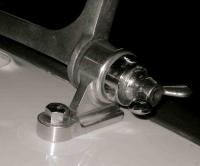
I adjusted the fan belt tension on my 4a today after a friend noticed that it was rather slack during a search for further causes of the apparent 'overheating' (now thought to be a duff gauge after changing senders, flushing etc and measuring temp of middle of radiator core at 60-65C when gauge off the scale). The result was evident when I took the car on a short run and heard a loud knocking as the dynamo pulley 'weights' hit the crosstube, but seemingly only when turning to the left. I had noticed witness marks on the crosstube previously but not thought any more of it. It seems that someone had positioned the dynamo to miss the crosstube with the result being a slack belt. I'm running a standard pulley and wide belt set up.
The dynamo pulley seems to be slightly out of line with the water pump and crank pulleys - although not showing this very well due to bad camera postion the photo attached gives an indication of what I mean. The pulley doesn't sit tight up to the dynamo fan - spaced off by about 3/16".
Is there something I'm missing like incorrect dynamo mounting or is this due to sagging engine mounts or some other well known cause?
Thanks in advance,
Rob.
Just another thought - The dynamo may be too close to the cross tube if the engine is too far forward because a 3 synchro gearbox mount plate is in use when a 4 synchro 'box is fitted.
TR2/3 suffer this way when a 4 synchro 'box is 'shoehorned' in without either filing the mount bolt holes 3/8" rearward in the gearbox chassis bracket or using a TR3B or 4 4 synchro chassis bracket. - The fan gets devilishly close to the radiator too making replacing the fan belt a struggle.
All because the 4 synchro 'box is about the thickness of a synchromesh cone longer than the 3 synchro. - almost 3/8" or 10 mm.
Cheers
Peter W
-
Hello Robert
TR3-3A-3B-4-4A with solid axle having round, 6 bolt end flange for hubs. (Girling Axle)
So you have removed all shims from both sides and reassembled the 2 axle shafts into the axle with bolts, and still can not get the end float below 0.005" total across the axle.
A worn thrust button is not one I have come across before.
Nicks or burrs on the mating faces? - dress clean with a file.
Are all the mating faces flat?
Have you lovingly painted the brake back plates, axle and hubs?
That paint coating could be the additional thickness you are trying to lose.
You may need metal to metal contact or as near as possible. Wipe the contact area clean with thinners or similar and try again.
Cheers
Peter W
-
Interesting...
If it is a post TS60 000 scuttle top it will have raised platforms/pressings for the bonnet hinges to sit on. Pre TS60 000 were flat.
The boot hinges also will have the raised platforms on post TS60 000 shells.
(That said I once saw a Dove Grey TR3A with raised hinge mounts one end and flat the other, when I work at C&B in Balham in the late 70's)
Any comments please?
Peter W
-
Steering racks add an amount into the bellows either end. Then add what you have chosen through the grease nipple point at the drive end housing via a grease gun point.
Trunnions - grease gun filled with your favoured lubricant through the grease nipple in the trunnion or vertical post. (changes from year to year and car to car)
Cheers
Peter W
PS the pain is getting oil into the grease gun........ very messy
-
You have a PM
Peter W
-
This is a good gearbox and it's very easy/possible to have this converted to TR spec fitment by ORS in Sheffield.
This is exactly what I have done for my TR4 rally car, and spare overdrive gearbox.
Once converted it will be far stronger than a TR gearbox and will fit straight in with no messing around with the input shaft, clutch, speedo drive or rear mounting. It will fit properly.
Talk to ORS.
David
I too have the Stag box in my TR3A with the A type o/d - I picked it up NOS from Unipart some years back when 'in the trade'.
Tony Dean at Kingston Sportscars did the swap over of the clutch/front shaft and replaced the overdrive unidirectional clutch for the modern bullet proof type.
Moss London did the speedo recalibration service for me.
It works a dream now it is almost run in.
Peter W
-
Interesting! I thought it was filled with oil and not just greased. I'll grease it tonight!
Thanks
Paul
I have always started with oil then greased in service.
What does the OE book say?
Next question should be what do you use in front suspension lower trunnions
Oil or Grease?
This is one where I have had to silver solder the end caps in the repro trunnions to get a good seal then EP 140 filled them in service.
Cheers
Peter W
-
Thanks for replying
Since yesterday I decided to go back to the begining and start again. I have refitted the original distributor in its marked position. I took the car for a short run and it is fine.
I put the car back in the garage and determined to find TDC. It is clear that it is not TDC when the pulley hole is lined up with the pointer.
Using a wire into cylinder 1 and a piece of lined paper taped against the plug hole I was able to find the TDC position. Using the centre line of the rotor I marked this position on the body of the distributor. The rotor was pointing to cylinder 1 position on the distributor.
I turned the engine over further to the position where the points open and marked this also. It was 30deg on the distributor from the TDC line.
(I did notice a white mark on the pulley about half way between these two positions but i don't know if it means anything)
So, having found TDC which looks correct relative to the rotor, can I just pull the old distributor at that position and fit the new one. (I will be using a new clamp so that I can remove the old distributor together with its clamp - just in case)
Your advice please
thanks
Steve
I first thought you had the distributor drive gear 1 tooth out
however
This sounds like the front pulley halves have been assembled to the hub one bolt hole out. You do have 6 holes to choose from! Also consider 30 deg at the distributor is 60 deg at the crank.
The drill hole in the pulley rim is TDC when the pulley is assembled correctly or I have been mistiming TR's for 40 years .
The drill hole in the pulley half should be in the same plane and opposite the woodruffe key slot of the pulley drive hub.
Maybe you could set TDC on your engine again and file a groove in the rim of your pulley, fill the new groove with white paint so a strobe lights it up better. Easier than unbolting the pulley and reassembling. Not as difficult on a wind-up window car as sidescreen. You can get the radiator out without major bodywork unbolting.
Cheers
Peter W
-
showing the location of the various plugs and grommets?
i believe it was a yellow car.
I put it in the Moss Europe TR2/3 parts catalogue. It is still in the printed version.
Peter W
-
Unbolted every injector with engine running. Fuel bursts out of every one with half a turn. Injector 5 I can screw off, hold in my hand and only the tiniest of drops comes out even at very high revs.
Ah the old No5 or No 2 problem....
Suspect the banjo bolt at the MU that holds the other end of the injector lead. It is a non return valve.
Remove, clean with a an with air line and refit - you can not get it to bits.
I think you will need a weird sized ring spanner for this - probably 3/8 or 7/16 Whitworth - Check first, do not ruin the hexagon on the bolt. - Good old Lucas........
Go through the above bleeding technique again.
If still no joy try swapping the banjo bolts - Nos 2 with 5 - to see if the problem moves to No 2 injector.
That will mean a replacement banjo bolt/NRV assy.
KMI always used to supply them. Moss Pt No 518630R
Once cleaned and refitted it is time to bleed.
Pull out No 5 Injector with the engine running.
Tap the injector on its side to see if it will start to spray
Does No 5 inj have a pointed tip?
If So also try
Holding it up in the air with a rag over the end,
Flick the pointed tip sideways to allow fuel to come out and hopefully bleed the injector.
Do this for 30 secs to 1 min to be sure you have fuel in the injector line and bled out any air.
Do not spray fuel at the exhaust. !!!
Hold injector close to the hole where it goes in the manifold and you should now see a nice cone of fuel spraying out.
Refit and enjoy your TR.
I wrote all this years ago and it is still printed in the Moss Europe TR5/250/6 parts catalogue - Get yourself a copy, it is more than a parts reference it is a users guide.
-
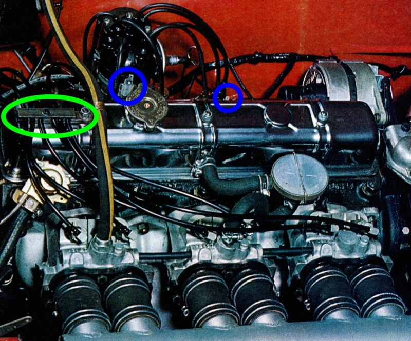
I agree, this hold-down clamp (green circle below) makes the injector leads look more tidy and prevents them from scratching the bonnet ... However, made of metal, this clamp must also be very good for conducting heat and vapourising the fuel!!!
And what about the low tension lead that should connect the two connectors in the blue circles below? Did the photographer need it to connect his flash to his camera?!?
I've read the previous threads on this and can only remark that the inlet mainfolds have no throttle spindles or throttle linkage either .
Also where does the Lucas PI MU get its manifold depression from to enable the claim 'fuel supplied to each cylinder is controlled with absolute accuracy under all operating conditions.'
Don't you just love it when the marketing dept. get in before the product is ready to go.....
At BMH we did a mock up MGF for MG factory marketing consumption to our test bed hack with the most outrageous black finish mag/alloy wheels and lowered the suspension to satisfy the demand that the wheels should fill the arches. It would not drive - we had let down the hyrolastic to get the desired effect.
Peter W
-
I left them out of my TR3 in 1975 and the car goes just fine today.
I guess they are there to enable a 'hot spot' between the exhaust and inlet, and perhaps to ease assy on the production track.
Cheers
Peter W
-
Thank you for the picture. These pipes appear to extend barely beyond the bumper. I'm not sure why mine extend so far, but I'll talk to the guy who installed them. I paid a pretty penny for the Abarth, and I want it to be right.
My brother and I loved these multi outlet exhausts when we were kids.
We could push loads of apples in them.......
however
Lolly sticks were best for ram pipes or 'velocity stacks' through bonnets on Ford E93A/100E 'specials' .
Peter W
-
So I have read the workshop manual and having been quoted what I think is lots of money to do the job,i have decided to have a go myself.
Before I start anybody done this already (successfully!!) who I can chat to,see if my theories on how to proceed without the factory jigs are correct
Before you ask why, its having an lsd fitted so have to start from scratch
regards Adrian
I did a TR Register Rebuild Seminar on this at St Neots some years ago, does any one still have the video?
Is your current axle quiet , without whining noises or clonks?
Are you intending to renew the CW & P or any bearings?
If NO to all of the above your task is a bit simpler, save removal and re-fitment of bearings without ruining them. ie. you only want to fit a LSD unit.
Before you take off the bearing caps mark them, so you putt them back in the right place, the right way round. That will save a bit of stress....
You will spend more time taking the thing to bits than rebuilding during the process. It is a slow and methodic job and needs constant attention.
NB - Check the CW & P tooth contact with engineers blue before you take it all to bits to see what it is running like and what you will expect to find once reassembled. It should not change if you do not move the height of the pinion, and you get the backlash right.
Tackle the axle in single steps when rebuilding.
Read and follow the factory workshop manual - especially the bits about pinion and carrier bearing preloads.
99% of the time a diff case spreader is not needed, just approach it with two tyre levers.
Bearing removers are needed - Do not just chisel them off !!!
You will need a dial indicator that measures in inches or a calculator to get the measurements from milli-metrics into inches. You will need a method of holding the drive flange when tightening the big nut. - I have a 2ft length of angle iron that bolts to the flange. You can just hold the flange in the vise but that takes away any 'feel' for the pinion rotation as it is tightened.
You will need a method of supporting the axle assy. beit bench vice or two quality axle stands and a clamp.
Have the skill to strip, identify, clean and inspect all the inners of the axle assy.
1. Set the carrier bearing (LSD) pre-load first without the pinion fitted. Fit bearings and shims in the same posn as they were in the orig set up. Then remove the LSD unit.
2. Fit and set the pinion pre-load without the seal fitted by adding or removing shims under the small pinion brg - you are more than likely to be removing to take up the wear, if you are not replacing the bearings. Work out the pre-load with a spring balance attached to a known length of bar attached to the drive flange. (you are looking for inch pounds of rotational torque) - The real tool is a bar with a known weight that can be moved along the calibrated bar. Once happy move onto fitting the carrier assy
3. Fit and torque the CW to the LSD.
4. Install the LSD and CW assy, set the backlash to the defined limit by moving shims from one side to the other - do not add to the shim pack that you selected to get the right bearing preload. Check with blue the tooth contact is as required. Remember you did a blue check before you stripped it.
5. Once you are happy, fit the nose seal, torque up the pinion flange nut and lock, lubricate the bearings and other moving bits. Fit the back cover.
6. Fit the half shafts, if a solid axle car, set axle shaft end float - a slow and laborious task. Fit new axle tube seals as required.
7. Refit axle.
8. Fill the axle with the correct LSD lubricant.
There, done in about a day unless you got all excited and wire brushed and painted the axle assy and had to wait for the poncing to dry.
What about the outer axle hub bearings??
Solid axle car owners - scratch head and search around for someone with a hub splitter. pm me if you are in need of an axle hub being split/removed, I have the OE Churchill tool.
Hope this helps
Peter W
-
Hi, my new tr6 was not happy and pressurising, diagnosed head gasket blown. Took it apart, head gasket was shot! Did very thorough job of changing all gaskets etc and dud valve clearances, rebuilt and now it is missing like hell! I think the miss is randomly shifting between cylinders but can't be sure, i m not a mechanic but I did the job with a 30yr time served technician, changed plugs again, done clearances again, put ht leads on, what am undoing wrong?? (was running sweet as a nut before head job)
Was the correct head gasket used?
Flat top or recessed top block? Check against the Eng No stamped on the block LH rear upper face. Get it wrong and the gasket blows........
Peter W
-
I need new carpets for the TR, where`s the best place to buy? I`m looking for reasonable quality at a sensible price, are Rimmers any good as they have an offer at present? Cheers, Steve.
Not sure what you mean by reasonable quality and sensible price. You get what you pay for.
What colour. What material. Will you fit them yourself?
Be aware the availability of correct coloured trim , few modern cars use black material now.
You are in Horsham and there is a company in Oxted in Surrey that used to make all of Moss's TR carpets, some of the seat covers, surrey tops, hoods, tonneaux, boot boards sidescreens etc..
The company advertises in The TR Reg Newsletter see page 30 of no.248 Traction.
They are Oxted Trimming Co. Tel 01883718530. they were the European Trimming stockist for the Robbins USA made softtops.
Link http://www.europeantrimming.co.uk/index.php
Link http://www.robbinsautotopco.com/index.php
Hope this helps a bit .
In my own car I have carpet on the tunnels and rear shelf and rubber mats on the floor. When they get wet (as so many TR s leak) they can be removed easily and dried, the car does not then smell like a rotting cabbage for weeks.
Cheers
Peter W
-
Good idea to check the crank end float. With the engine stopped try to lever the crank forward and back- Do not get too excited and bend the pulley with your lever though.
There should be no visible (or audible) movement unless you have laser beam measuring eye sight and can distinguish 0.004" to 0.006" !!!
Check also the water pump pulley is not wobbling or loose on the pump shaft. This is relevant to water pumps with a detachable pulley. Release the tension on the belt, grab the pulley a feel if it wobbles (engine not running), also try tightening the pump pulley nut . I have experienced this a few times over the years and it sounds horridly expensive. The pulley runs loose and the woodruffe key in the pump shaft eats into the pulley. I suspect that problem was always caused by over tightening the wide fan belt. Cure is a pump and pulley assy.
Cheers
Peter W
-
The manuals I have giving the Tr3a tappet clearance are conflicting, one is 016" inlet and 010" exhaust, the other says 010" for both inlet and exhaust.
Which is correct please, again thanks in advance.
Alexander
This may all depend on what cam shaft you have fitted....Is it standard?
My TR3 with 'sporty' non standard cam runs 0.018" inlet & 0.020" exhaust.
Peter W
-
All the motors have a park mechanism, just take off the silver gear plate (as per your photo) there will (or should be) a brass/copper spring loaded contact which can sit in two positions. It might have broken its locater contact or be fitted incorrectly.
Cheers
Darren
The photo shews the gearbox cover to be an all pressed in one aluminium thing not the two piece steel arrangement found on the more common type. The round steel part of the two piece arrangement with a wire attached being the adjustable parking switch.
The last wiper motor of this style with an aluminium gearbox lid that I repaired was allegedly from an 'ex works Mini Cooper S', and that did not have self park either. The owner advised me that it enabled the wipers to be positioned wherever the occupants fancied - very Abingdon ......
Other parking devices include a screw and spring arrangement into the end of the gearbox next to the rack outlet. OR the reversing motor. The motor photographed has insufficient wires to be like the Jag/Rolls arrangement that reverses when the switch is set to 'park' and parks the wipers off the screen.
Strip the motor and post some photos so we can do a repair by internet.....
What was original on 4VC? or any other real works TR4 s.
Peter W
PS - CRT Type wiper motor from TR2/3 did not self park either.
-
Can anyone direct me to or provide info on converting from H6 to HS6 SUs? I see in the forum lots of posts addressing the innards, needles etc. I am looking for help in modifying or swapping out the throttle linkage, from end pull to center pull.
The rod from the bulkhead to the centre bell crank is shorter by an inch or two, the upright rod can be adjusted to suit.
If you are putting HS on a TR2/3 you may find the rear float chamber of the HS is very close to the heater feed through the bulk head. I modified mine to the 'two on one side' bulkhead connector arrangement from a TR4-6.
My car runs a cable linkage not the rod arrangement.
The H type choke wire is barely long enough, you may need to lengthen it.
Ashley James photo shews it all very clearly.
Anyone out there got a spare TR4A inlet manifold, a buddy of mine rebuilding a Peerless is looking for one. - PM me.
Cheers
Peter W
030123 WASHER, lead linger/wire
in TR2/3/3A/3B Forum
Posted
Yes solder will do.
I have a couple of actual NOS rolls of 30123 Lead Linger in the garage - if any one wants to buy a foot or two. I have recently used some under head nuts and the Oil pressure relief valve lock nut.
Cheers
Peter W