

Malbaby
-
Content Count
809 -
Joined
-
Last visited
Content Type
Profiles
Forums
Calendar
Posts posted by Malbaby
-
-
-
Racestorations UK have a good reputation for quality.
-
Make sure the doors are aligned in height with the wings along the swage line before drilling.
-
4 hours ago, jerrytr5 said:
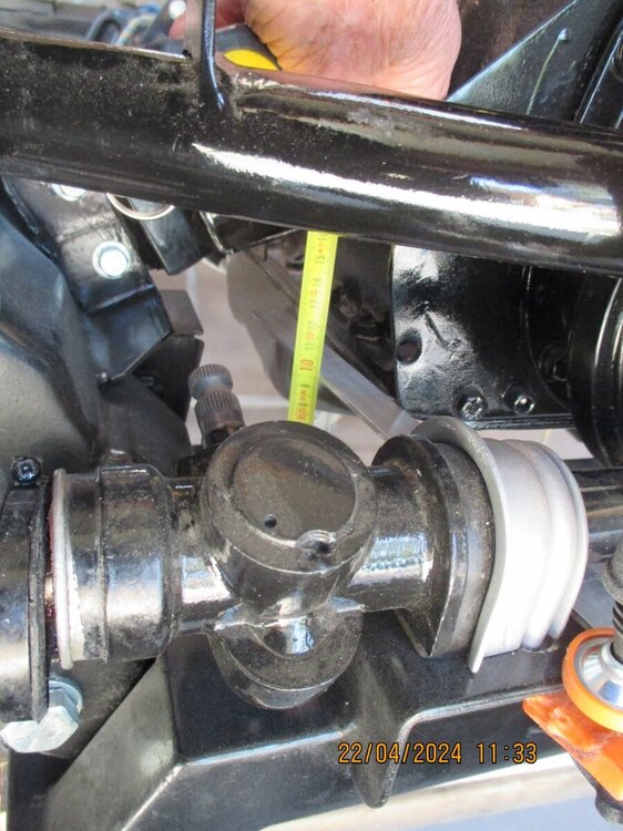
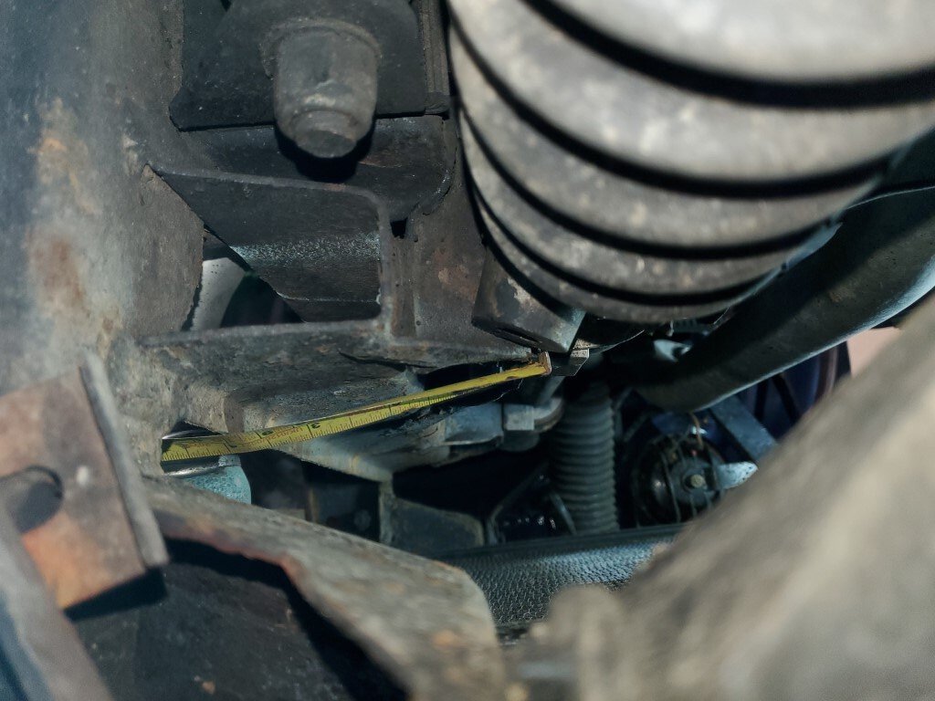
Quite difficult to do on a running car, however using the main chassis crossmember as a datum point I get the following:
Rack mounting plate to bottom of cross member 173mm. Using straight edge clamped to cross member.
Rear of rack mounting plate to front of cross member 85mm. Using plumb line.
Not too accurate so +/- 3mm I would guess.
Jerry

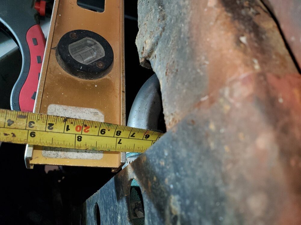
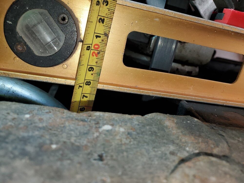
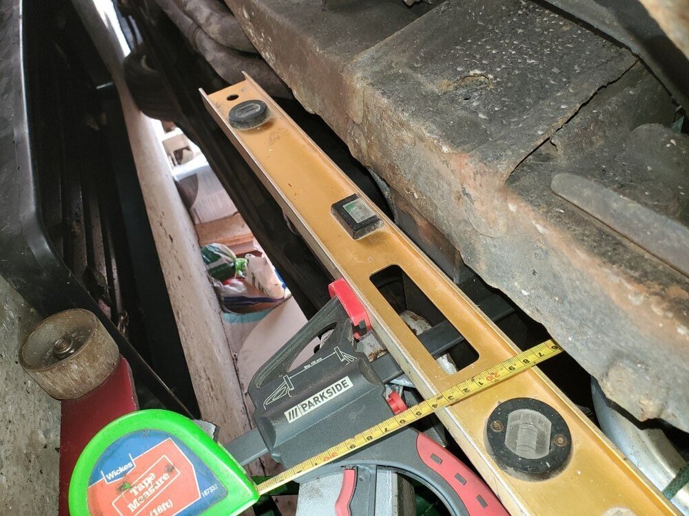
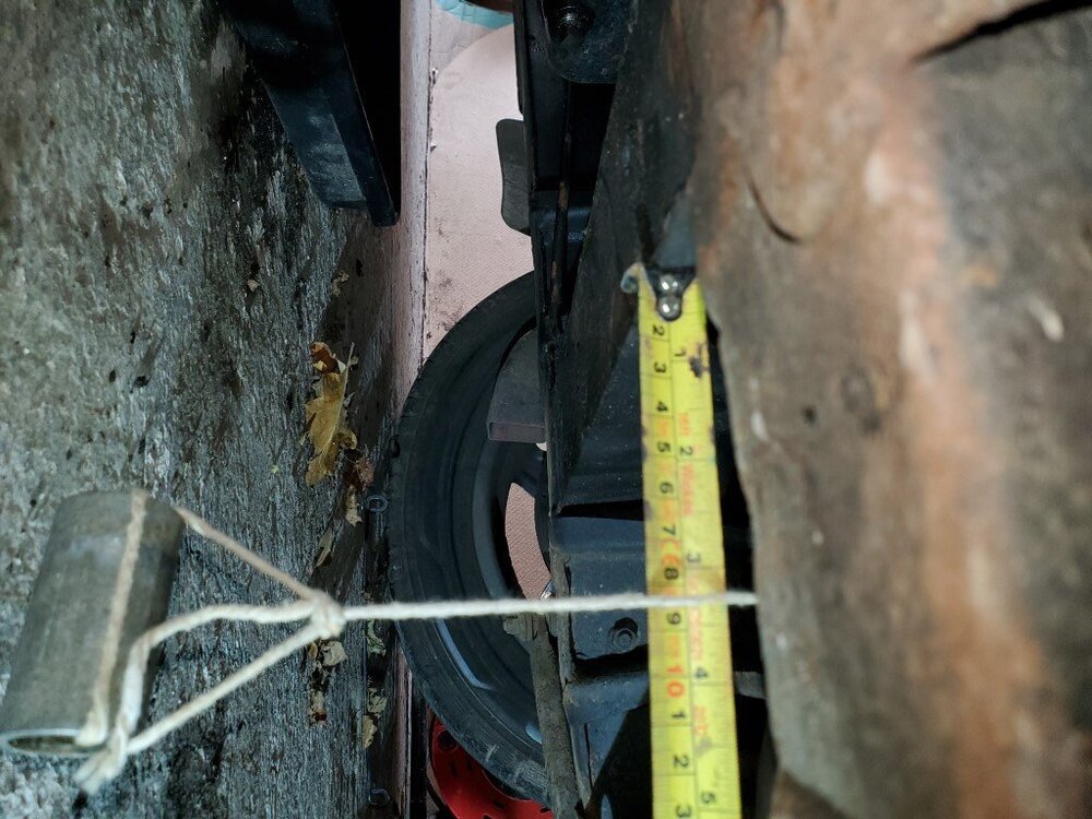
Thanks very much Jerry, very helpful.
-
Getting desperate..

-
16 hours ago, Z320 said:
Hi Malcolm,
I would help you, but I own a 4A…
Good luck for your car registration
Marco
Thanks Marco...hoping someone on here that currently has a bare chassis can help out with measurements and pics.
-
Rimmers premium can be problematic.
-
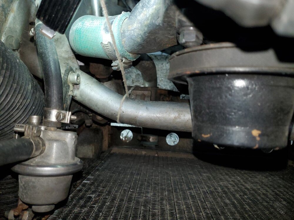
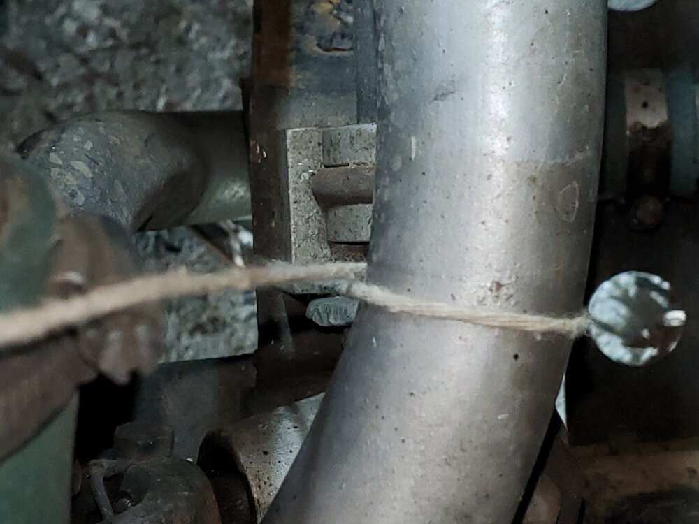
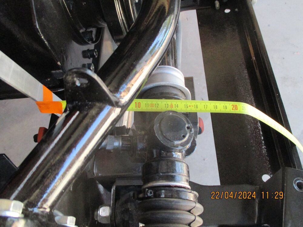
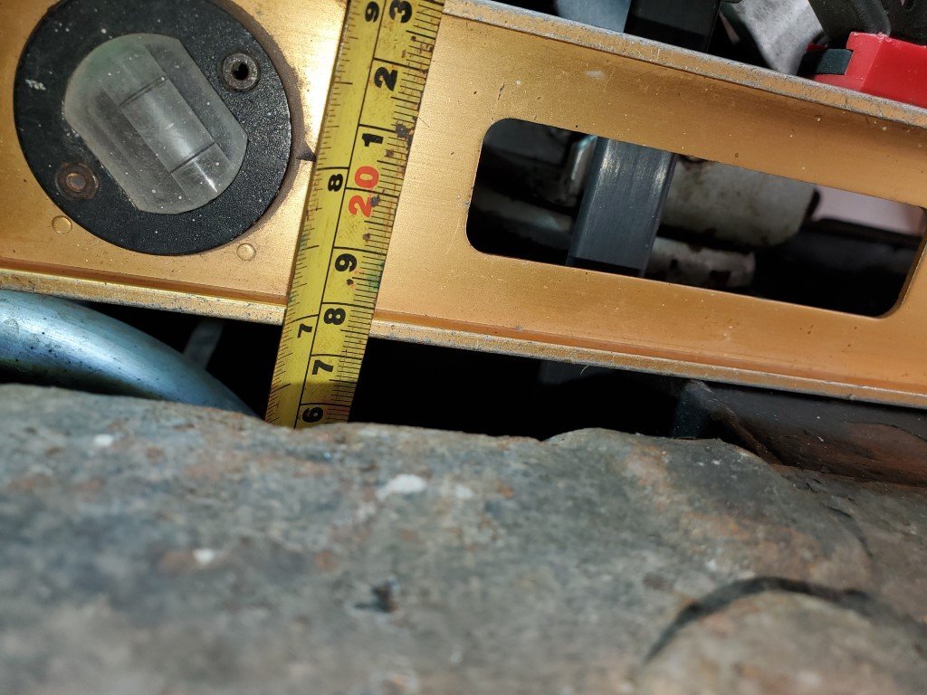
Can anyone interpret the height measurement of the steering rack mount plates in relation to another part of the chassis from the workshop manual, pictured above.
-
Hi Guys..
My project car...TR4A with 6 cyl TR engine.
I am confident that I have the rack in the "factory" position, thanks to very helpful forum members that provided the measurements.
Currently the "Certifying Automotive Engineer" that I have to use in order to eventually have the car registered requires documentary proof of what I have done is the correct factory position..
I have seen the factory chassis measurements diagram, but the rack location/mounting plate face is not clearly seen.....Usually in relation to the main front cross member.
Are there any "factory" or workshop manuals that give the precise location.Or, is there anyone that can take some pics together with ruler/tape measurements on their TR5/6.
.jpg.d4d39b432ee2ab57322ea19655ab536a.jpg)
-
Hi Dave...I am at a similar stage to you.
Do you plan to fit the body before mounting the engine and transmission....[Much easier afterwards].
Also....I have private messaged you.
-
"Harry TR" has the best advice....What you have now is the appropriate and best looking option.
Sell the "new" ones.
-
Be aware.... The dash pads that I bought from Rimmers were moulded plastic
-
Malalignment of the front body panels would really annoy me.
-
I fitted good sized washers under the bolt heads.
-
Thanks for the replies...pity the RHD steering column limits the selection somewhat.
-
So it's a USA TR250, not TR5??
Was it previously a LHD car??
-
There are a few on the market.
Which one is the best value for money?
-
Thanks Harry, I do not need the measurements of the brace itself, just its relative position.
-
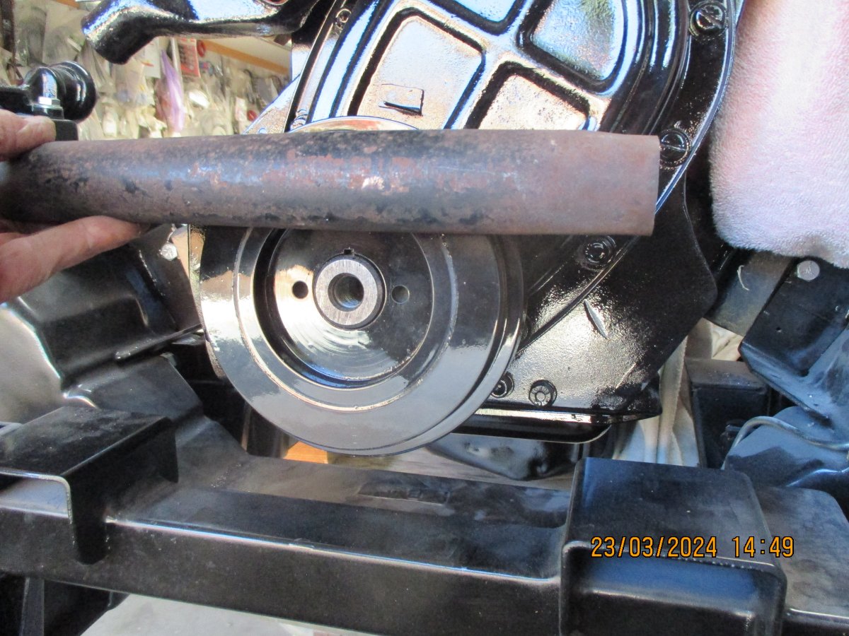
I am fabricating a new tower brace for my project car and would like to know the relative measurements to the centre and face of the harmonic balancer.
Intending to fit a thermo fan so the engine fan/extension is not required.
Presumeably leave just enough space between the balancer face and the brace for the fan belt fitment/removal.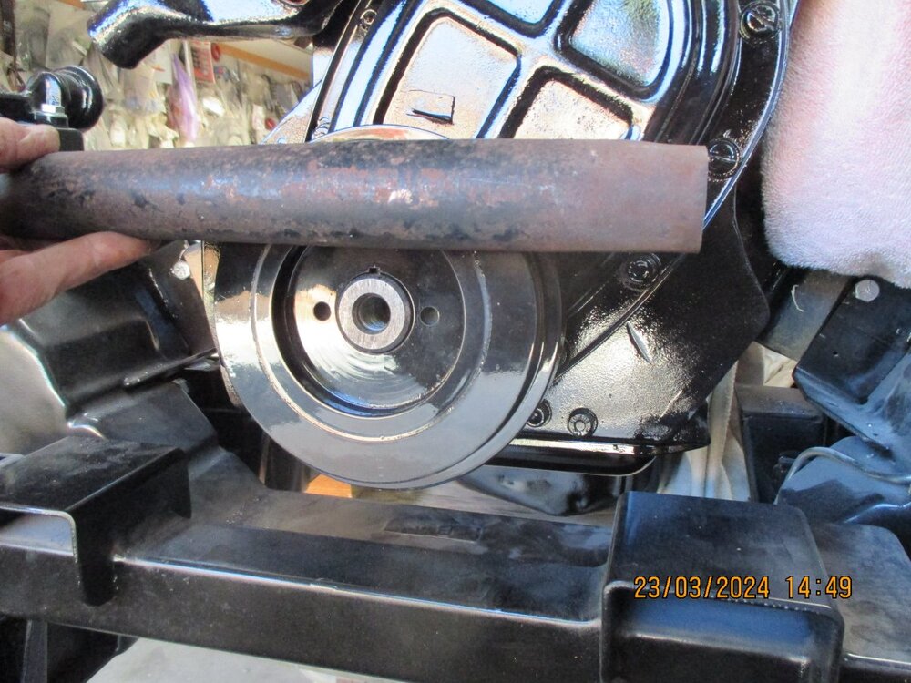
-
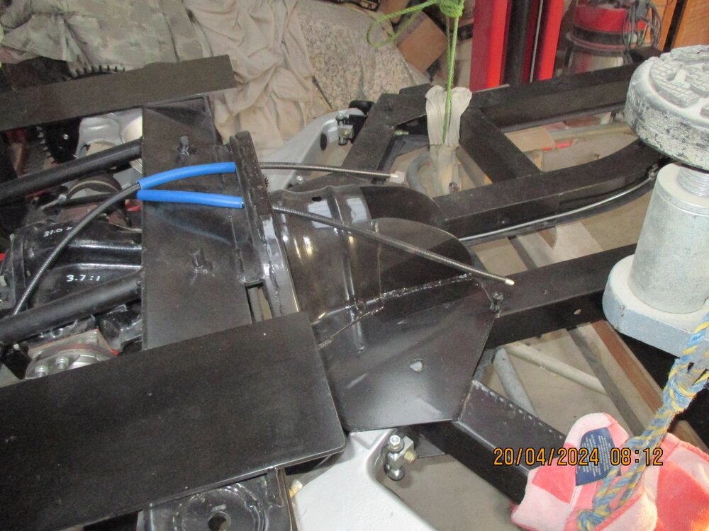
Does anyone know where the power rack that CDD uses is sourced from.....must be from a manufactured car.
-
I am all for sensible modifications, but I would keep the current diff if it is Ok.
The diff replacements that I have seen.. eg..Nissan or BMW, the bracketry for attachment does not look as good as the factory install.
Different story if you want an LSD.
-
9 hours ago, david ferry said:
Unless I'm missing the point here, would a good start point not be the location of the engine mount chassis brackets on either a TR5 or 6?
Given the road wheels are in the same place on all chassis, wouldn't that then mean that your engine is in the same/correct location and you can then modify other sections of the chassis around the engine, if needs be.
I think that this would be the way that I'd be doing this.
Are the required measurements/chassis bracket locations and holes to be found in workshop manuals?
David
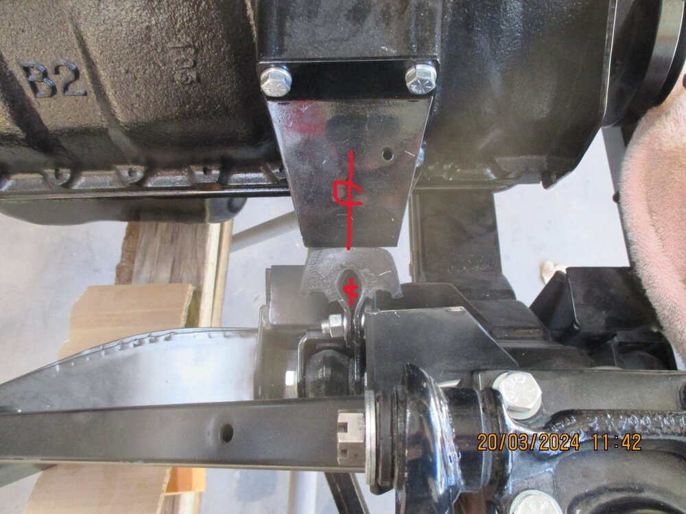
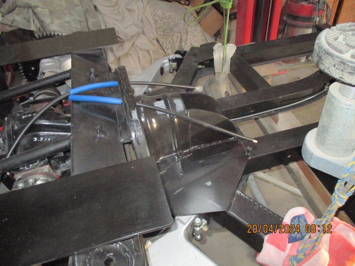
Hi David...I had to fabricate new engine mount to chassis plates as they are not available to purchase, then welded them on to where I believed [on advice and measurements from forum members] was the correct position.
I now just wanted to double check that I have it right, hence my post.
-
11 hours ago, mleadbeater said:
Malbaby
can you give use some more details as to why?
cheers
Mike
IMHO.....The light guage steel bracket that is attached to the firewall to bolt down the column was OK back in the day, but not these days.
All of the aftermarket EPAS systems that I have seen only have an additional steel stay attached as support for the steering column.
There is column torque generated by the unit and should be addressed properly...eg..delete the existing firewall bracket and bolt/weld in a substantial dedicated bracket.
The price of the "Ezpowersteeringuk" unit is OTT, whereas a unit such as "Z320's" can be fabricated at a much lower cost.
"Stuart" is correct regarding tyre size.
-
4 hours ago, Waldi said:
Hi Malbaby,
I measured my CP-TR6 this morning.
The lower block flange is 90 mm above the crossmember, the ridge of the sump around 10 mm lower.
I assume the sump dimension you give (50 mm) is related to the other dimension, and was a bit hard to access now, or do I mis-understand you?
The engine rubber mounts are 7 years old now sow will have sagged a bit, but not much, maybe just a couple of mm.
The block is sitting level left to right but the rear end is lower compared to the front.
Hope this helps.
Waldi
Thanks Waldi....the bottom of the engine block is 80mm above the CM, so I should be OK with height.
As for checking the longitudinal placement?....the centre of the engine mount is very close to be aligned with the front edge of the rear lower control arm bracket on the chassis.


Help with steering rack position please....[again]
in TR6 Forum
Posted
Thanks for the offer Marco......My problem has been solved with the generous assistance of this forum.