


Lebro
-
Content Count
12,040 -
Joined
-
Last visited
Content Type
Profiles
Forums
Calendar
Posts posted by Lebro
-
-
Oh I see ! Had not realised the cam could be placed in two different places on the gear. Silly me !
Bob
-
Just though of something else.
If you existing clutch cover is the coil spring type, then either the release mechanism in the gearbox will have to be changed to match, or, you will have to fit a diaphram clutch cover to suit the gearbox. This latter option will mean re drilling the flywheel as the holes are not in the same place.
An alternative to using an adaptor mount for the overdrive would be to have it re-built with the correct rear casing. These are used on TR's & Healey 3000's
My local gearbox specialists (Hardy Engineering) rebuilt mine (I have a 2000 box in my TR3) with the 3000 rear casing, & also added parts to bring it up to TR spec. They did not change the speedo drive (I guess they could have done) so I had to modify my speedo to read correctly (another story !)
Bob
-
Makes no difference where you put it, The motor will always stop (park) when the cam pushes the switch pin down.
Looking at photos above, that will be when the cable end is pushed fully out of the motor.
Bob
-
Other things to consider, the rear flange on the box has the wrong hole spacing to fit the TR propshaft. The speedo drive is a 3.5:1 reduction whereas the TR setup is 2.5:1, so speedo will read slow. Finally the clutch is different, but simple fix is use the 2000 friction plate in the TR cover plate. The overdrive is not as strong as the TR one, & so is only used on 3rd, ,& 4th gear.
Bob
-
They are available from TR shop etc.
Bob
-
-
OK. Have ordered one of each anyway, I don't mind having then "in stock". will let you know how it goes.
Bob
-
Don't worry, Duncan probably won't have an answer for dimming them. I will order a pair, & do some tests.
Bob
-

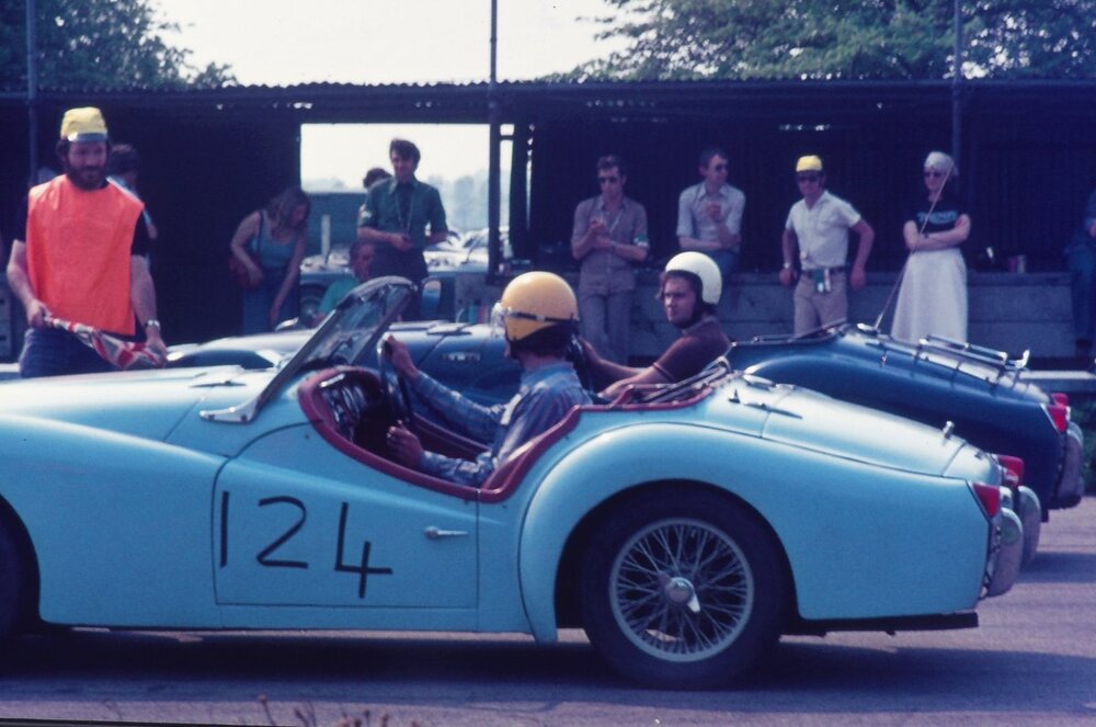
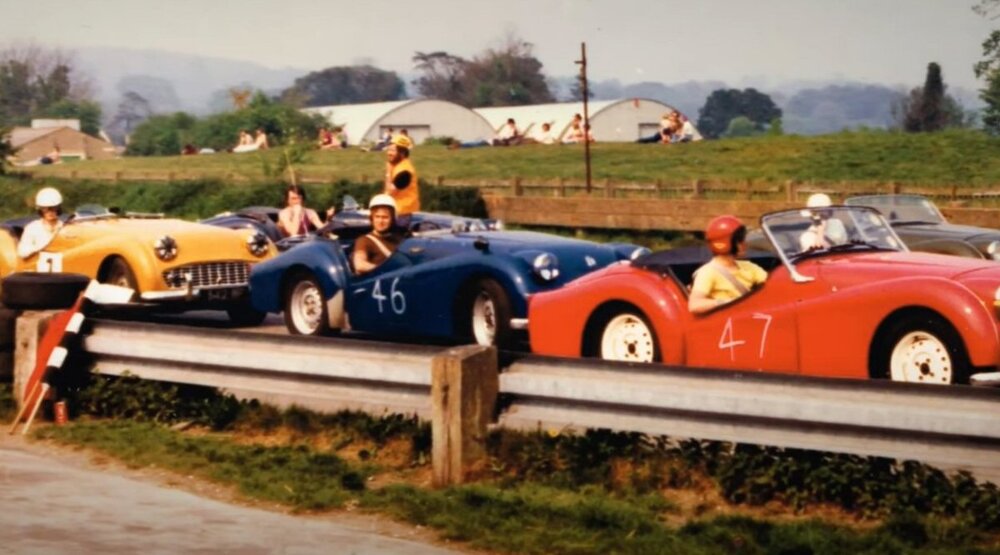
SWMBO driving car at Donnington '76 Me at Goodwood '76 (background) Me again behind Niel Revington Goodwood '76
-
Ok a little concerned about the mix of LED bulb types, I may buy one of each so I can check that they dim to the same extent as each other with reduced voltage. It may take a week or so, but will get back to you when I am confident I can do what you need.
Bob
-
Where are the capless canbus ones used ? Sounds wrong for a TR4 !
-
Can't be the UK, as it's not raining

-
The circuit it clearly meant to control the speed of a motor. I'm wondering if the LED's are providing sufficient load for the circuit to work properly..
Harry. I can make you a simple dimmer if you like, can you detail exactly which LEDs you want to use, & how many. Also not having a TR4 I am not clear on what the normal dimmer (or switch) & knob look like, & how the knob is attached to the switch (or dimmer)
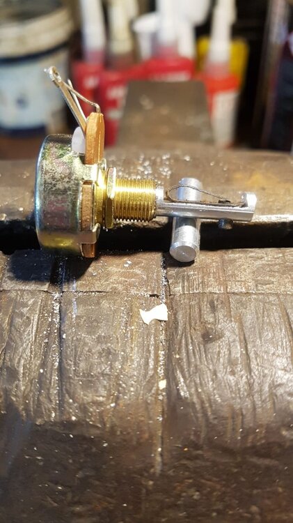
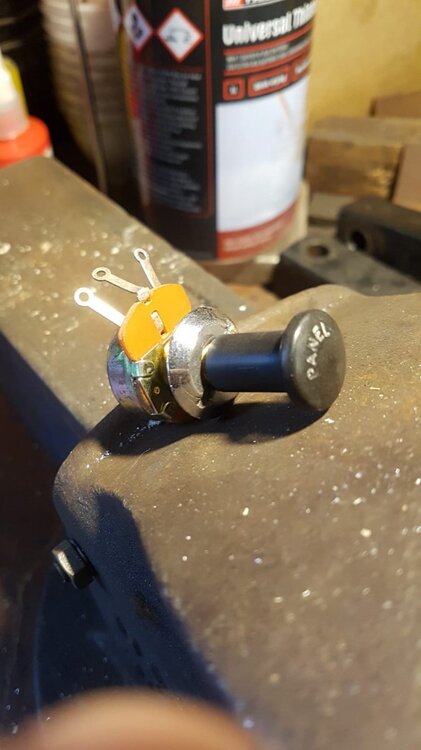
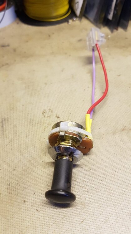
This is how I did it for my TR3
Bob
-
He seemed to put a lot more effort into removing the offside spinner then when he replaced it - enforcing the "self tightening" theory.
Bob
-
I had occasion to compare readings from my Lidl digital caliper against a Mituyoyo digital micrometer which I bought second hand. The resolution was not there, as not as many decimal points are shown, but it was totaly accurate. quite impressed by that for such a cheap device.
I used to be able to easily read the vernier scales on these things, but these days it's a struggle without a fair amount of magnification, so a digital version makes life much easier.
Bob
-
Agreed, I changed mine for a "C" pin years ago. Just saying that almost everyone calls the "C" pin a Mills pin these days.
Bob
-
I sure you are correct Mick, but everywhere I look on the internet describes the Mills pin as being the "C" type you describe. & that is what Rimmers are selling to do this job. Maybe the definition has become corrupted over the years.
Bob
-
Yes, that's the one. Easy to put a new one in, more difficult getting the old one out as I recall.
Bob
-
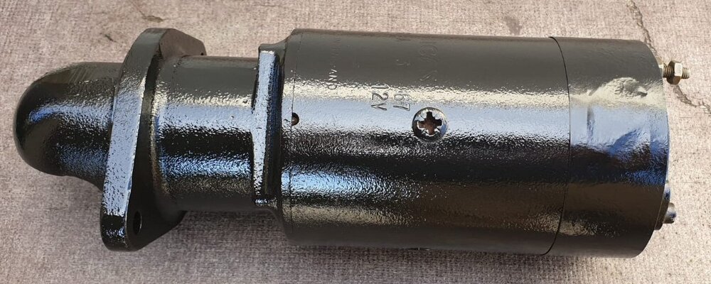
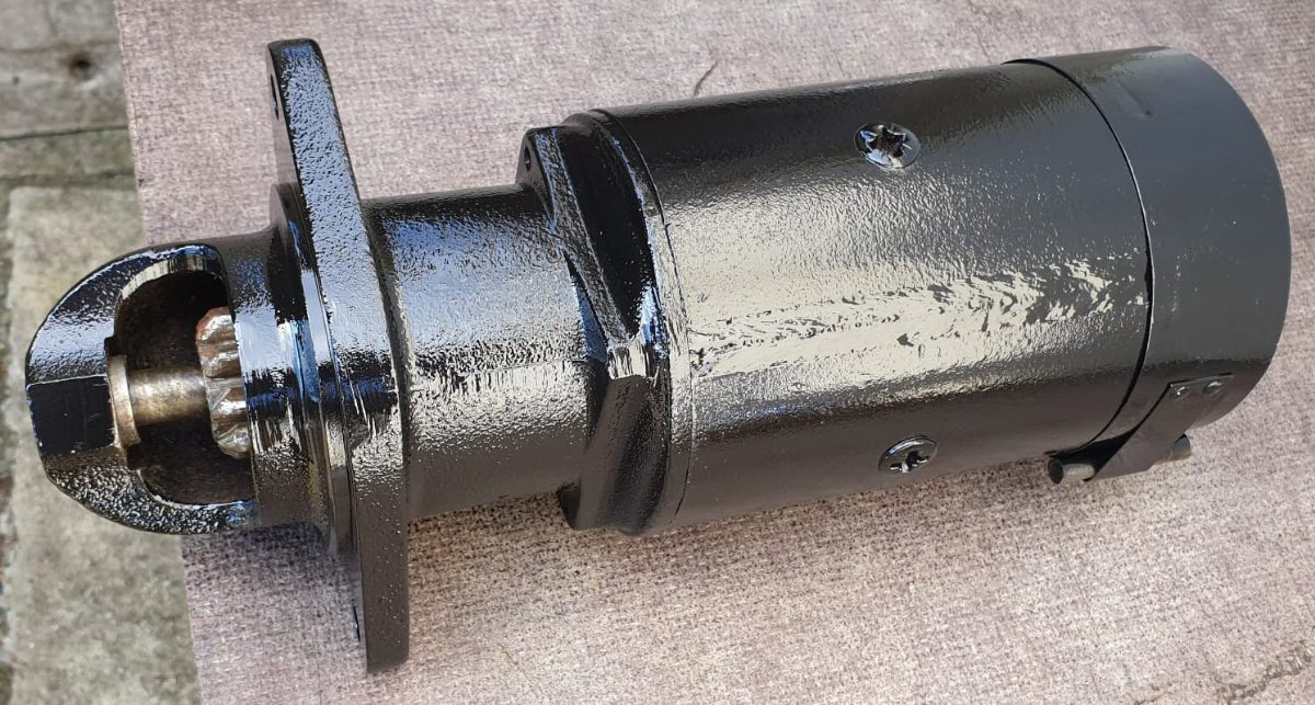
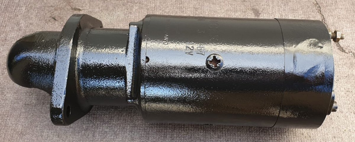
I think any of the "high torque" motors will give you good clearance. I have the same manifold, with a Wosp starter motor & plenty of clearance.
Bob
-
From previous experience with my Daughters 70's mini it was the nearside Bush at the end of the rack which was badly worn, causing mot fail.
Bob
-
Good tested & working Bomb starter motor (9 tooth for shrink on ring gear) £50

Bob
-
Beat me to it. Symptoms suggest open circuit between tank sender, & "T" terminal on gauge.
1st check when in fault mode (full tank showing) would be to ground the wire going to the sender at the sender. Gauge should go to empty.
Bob
-
Me too !
Bob
-
The biggest mistake may have been removing the field coils from the casing. They will be difficult to replace such that they do ot contact the spinning armature.
Regarding the insulation test, 2.5k is no where near high enough but you may have just been measuring yourself ! If you were holding the probes onto the armature with bare fingers
Bob


Triumph 2000 gearbox
in TR4/4A Forum
Posted
If your original box is an overdrive one swap the TR overdrive onto the 200 box, & swap the clutch release mechanism, & use T2000 friction plate in original clutch.
Bob