


NCS_TR3A
-
Content Count
165 -
Joined
-
Last visited
Content Type
Profiles
Forums
Calendar
Posts posted by NCS_TR3A
-
-
10 hours ago, John McCormack said:
I think Bob (Lebro above) and a few others theory of the solenoid being kept up by debris in the solenoid (which is open from the bottom) is most feasible.
Hi John, I guess it depends on the type of overdrive. My A type solenoid has a rubber seal at the bottom to stop the dirt getting in. I don't know if the J type does or doesn't. I had overdrive on my Jag Mk2 as well and that had a seal as well. Worth checking if you are meant to have one on as it may stop a repeat.
Neil
-
On 3/31/2021 at 11:25 AM, RobTR3 said:
Neil/Roy
I did this job a couple of years ago and I definitely removed the cover plate, as far as I can remember to get at the o' ring. I don't remember it being on the outside of the cover plate. The diagram in the Moss book, does show it on the outside which is a bit confusing admittedly. The only other reason to remove the plate would be to renew the gasket, but it was a leaking o' ring I had to replace. Perhaps other members can clarify.
The o' ring on the R/H side is a tap out of the rolled pin on the adjustment lever, which is then removed, and the o' ring pushed on. I did this one as well.
Rob
Rob, thanks and your memory is correct. I took the plate off today to check and have attached the photo that confirms the seal is on the inside. I thankful you posted this before I was ready to refit, a far easier job on the bench. I did follow the process of removing the bolts a bit at a time due to the spring that sits behind it. I do also note that the o ring I have from Moss is not quite the same shape as the one I took out. The old one is more of a square section and thre moss one is more a normal (circular) one. Need to get a new gasket before refiting but thanks for positing the correct method.
Neil

-
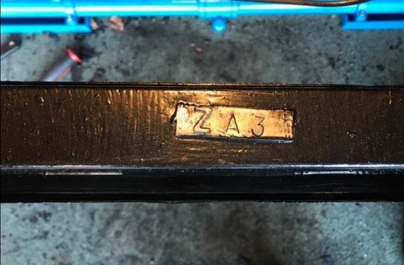
Thanks gents, it is indeed a 1959 car, it's actually just before 60000 (just a few before) and it has the post 60000 body as well. I have no idea if it's all original or not. Obviously the numbering system is not as straight forward as I assumed, ie ZA1, ZA2, ZA3.......
Neil
-
Does this mean anything to anyone. I've searched on the forum but I cannot find any information. I assume it's a plate that confirms the design number (ie this is the third generation or update) anyone know for certain what it means.
-
Sorry to add yet another post but I went looking for the answer rather than relying on memory. I quite often use SC parts site for things like this as they tend to tell you the thread on the items unlike Moss.
Based on this it should be a 3BA which is what I remember mine being as well.
Neil
-
Looking on ebay there seems to be a lot of 2BA instrument nuts, although there is one that's M5 x 0.75 tread (which is slight odd as M5 is 0.8) so I might have totally the wrong memory on this
-
Mine were definately a BA thread. I thought they were 3BA but that would be about 3.9mm shaft, 2BA is 4. 5mm shaft so based on your M4 nuts only going on a turn its probably a 3BA. I couldn't find a wing nut in BA when I was looking so I tapped them. A lot easier with wing nuts, just don't over tighten.
Neil
-
Getting the jets to return has always been a challenge for me. Even with new springs everything has to be just right for the choke to return fully. That's was one of the reasons I was trying the vitron, less friction than the cork. You did leave the cork in fresh engine oil overnight before fitting? That's a must.
Neil
-
Richard,
Do you need any measurements of parts. My carbs are presently off and I intend to strip the bottom again and see if I can fit vitron seals with them leaking (which they did first time) but it seems that everyone else has been successful with this so I should get it to work.
Neil
-
9 hours ago, BlueTR3A-5EKT said:
Hi Neil
This has been covered before.....
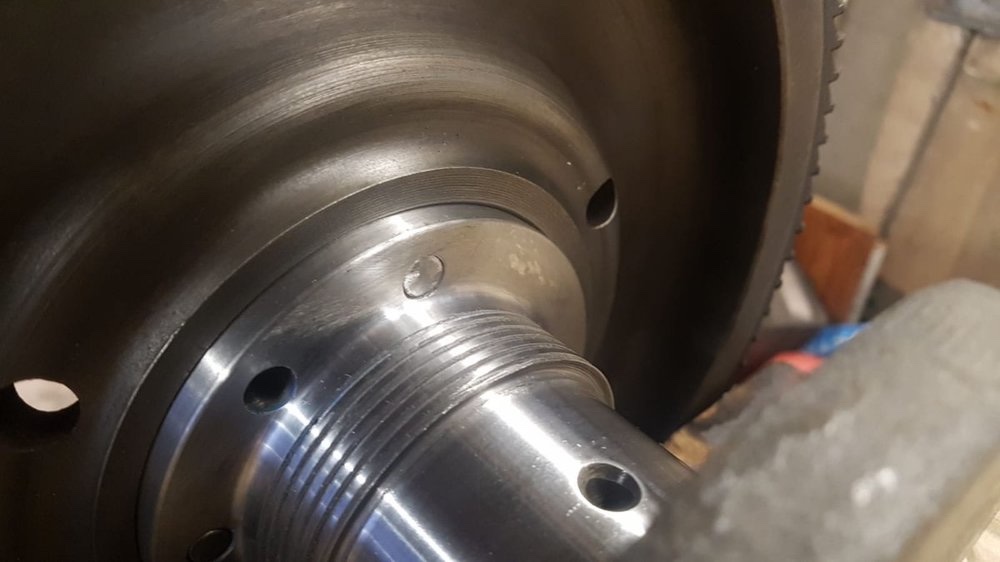
Not sure if you rear oil seal instructions include this but the flywheel bolt length must be checked that it does not protrude through the crank rear flange and touch the new seal housing.
Peter W
Thanks Peter,
I've read a lot on the upgrade and had picked up the bolt clearance check. Whilst I've done a lot on cars I've never actually taken a bottom end apart before so it's going to be a journey for me. Head stuff quite a few times and bodywork etc but never into the main part of an engine (or into the internals of a gear box either but not doing that this time). At the end of the day it's mechanical and if you take your time and follow the rules it generally OK and always seems more scary than it really is. Fingers crossed. Bolts ordered to mount the engine and plenty to done to keep me busy
Neil
-
3 hours ago, Lebro said:
I used some 5/16" cap head high tensile bolts, from here : https://www.ebay.co.uk/itm/114282833207
Bob.
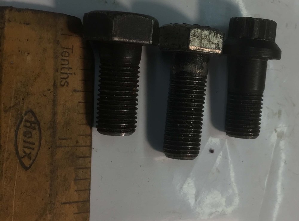
Thanks Bob, similar set up but I think I need 5 inch bolts due to the length of the tubes on the stand. I like the stepped washers you have made. Looking to do the same as those tubes are 16mm ID so plenty of opertunity for the load to shift as you turn it over.
I'm sure I'll be back for more advice as I try to strip the engine further.
Neil
-
Thanks Mick, if its 120 lbs ft to tighten I bet its a lot more to get it off. I'll get myself The worst I've had is on my sons car, a 2005 Freelander front wheel hub nut which was 295 ft lbs. Didn't have a torque wrench for that one, had to work out a way to do it.
Neil
-
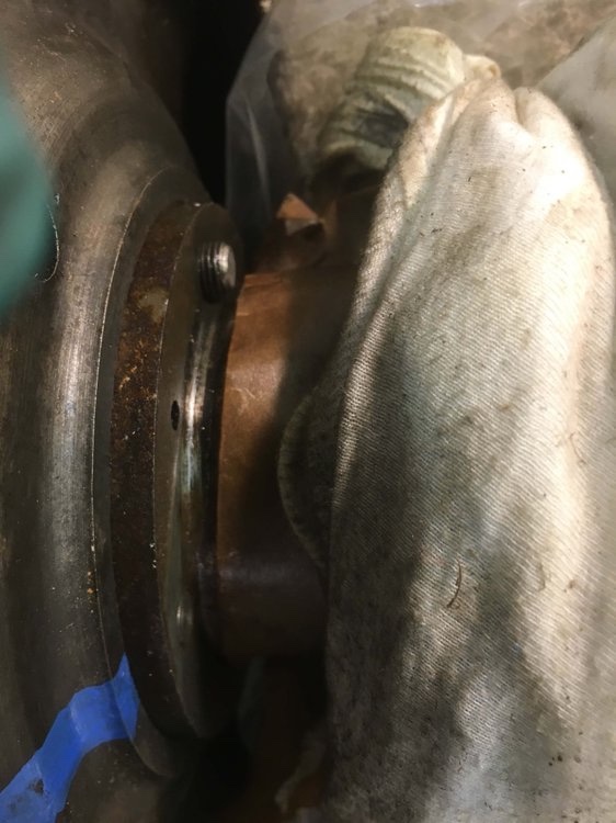
7 hours ago, RobTR3 said:
Item 55 is an o' ring that is probably the cause of the leak. You will need to take off the solenoid and the bracket/cover plate (53) two bolts and two nuts on studs, release them evenly as there is a strong spring pushing behind the plate. The o' ring is pushed on to the operating shaft and forms an oil seal when the cover plate is tightened up. Renew the gasket 52 and fit/ re-adjust the solenoid. Good luck.
Rob
.
Rob, I'm hoping you are mistaken on this as I've just done this job and I did not remove plate 53. I think it's just a case of removing the actuating lever (57)and then the collar (56) and you can change the o ring (55) and put it all back together. There is an o ring on the other side which requires a pin to be tapped (quite a bit of "tapping" in my case).
Both o rings were missing on mine, probably gone hard, cracked and fallen off. I hope I've got this right and the seals should be on the outside and not the inside but please correct me if I'm wrong. Easier to fix whilst it's still on the bench.
Neil
-
2 hours ago, Drewmotty said:
There’s something wrong there Rich. The jet should come up near flush when screwed right in. Are you sure that it’s assembled correctly and that the choke is fully seating?
Agree, mine are nearly flush when fully adjusted up. I think that will be your problem and certainly explain why rich.
Neil
-
Gents,
This site has been great to find information out and learn from those that have been there and done it. I took the gearbox out several weeks ago and changed seals etc (it's all in good condition but did leak oil). It appears the main source was the selector shafts and I have copied a few good ideas on here and that's now all done and ready to go back in.
However I've decided to take the engine out and change the mounts, the front crank seal and probably a Mad Marx rear oil seal as well. Oh and this will probably lead to a bottom end overhaul just by the very nature of the work. It's a first for me so will be taking it slowly.
I'm at the position that I have the engine out, but I'm looking at how to mount it to an engine stand that's new to me. I'm assuming that you mount on the gewr box end. The bell housing bolts are 5/16" UNC 18tpi. They would need to be about 4" long to go through the mount plates.
Is this the right way of doing it. 5/16 seems a little slim to me but I cannot see any clever alternative??
Neil
-
Richard,
Normally the petrol level would be below this seal, only really going above it if the needle fails to seal and then the float chamber will overflow. You could have a go at making a gasket but that is a pretty thin gasket to seal. Without the right seal a small amount of silicon sealant would be OK I think.
Neil
-
I had all this off earlier this year but still cannot remember if I used a ball joint splitter. I don't remember using one but I have a few so might have. I think I just undid the nut and prised it out. Removing the damper I do remember. There is a bolt that goes in from the other side. It's the bolt you turn but you need to hold the nut. I think I was able to get an open ended spanner on it from an angle but a box spanner or socket with a 1/4 inch size extention (to give the space past to casing) would do it. It doesn't stick in my mind as being to difficult.
Neil
-
4 hours ago, Tom Bryant said:
A few comments:
1. Lots of luck with the Viton. They don't work. Well, they might seal the leak, but they have too much friction, and the jet won't return.
2. PTFE (Teflon) does work, but you need to install two of them in place of each original cork jet seal. And, of course, the two dished washers must be installed the proper way around.
3. Neil's problem (with leaking Teflon seals) is not the usual outcome. I've installed thousands of the Teflon o-rings, and although there have been a few leakers, all of them were due to some sort of fixable problem, sometimes a mistake of my own, never the PTFE o-rings themselves. I suggest he try again, and if there is a leak, look for the source of the problem, and not give up until he finds it, because it will be fixable. And, once properly fixed, those PTFE o-rings will not fail in your lifetime. The holes in the sides of the jet should be chamfered with a file to remove the sharp edges so they don't cut the PTFE seals as they slide over the holes.
5. Back to the OP (Chipperman52) and the loose conical ring above the gland nut: Sounds to me as if the cork ring itself is too thin. I always toss those in the trash and replace them with a 1/8" X 3/4" ID ("Dash 210") Buna-N o-ring. That should do the trick.
6. Don't even think about tossing that copper washer above the upper jet bearing. It's absolutely necessary for two reasons:
a. It seals the jet bearing so that fuel doesn't leak around it and past the jet orifice, upsetting the air/fuel mixture. Leakage here will not come out the bottom of the jet where it would be visible, but it could make it difficult (or impossible) to get the proper air/fuel mixture.
b. It must be present (and of the proper thickness) to lock the whole jet bearing assembly in place so that the jet adjustment nut can be turned without also turning the male-threaded jet bearing itself. "Proper thickness" is 1/32nd inch (0.031") no more and no less. Many repair kits come with a much thinner (typically 1/64th inch) copper washer. That should be either thrown in the trash, or if necessary, doubled up to get the proper 1/32" thickness. Replacing that 1/32" copper washer with fiber is, well, just plain silly. Don't do it. (Even if that copper washer did leak a smidgen, you'd never know it by examination of the bottom of the jet. Any leakage would be upward, into the throat of the carburetor. Small amounts of leakage past that copper washer, if it should occur (unlikely), would not be enough to upset the air/fuel mixture. So... there's just no reason to ever even think of using a fiber washer there.)
7. In answer to Neil's comment:
"I'm struggling to think why the bottom nut would be tight before you got enough pressure on the cork seal and washer to stop it spinning."
It's not the pressure on the cork seal that prevents that male-threaded piece from turning; rather, it's that 1/32" copper washer that keeps the thing in place and prevents both turning and leakage. It's also quite possible for the cork seal (or Buna-N o-ring) to be "wicked tight" and the upper jet bearing to be loose and leaky, particularly if that 1/32" copper washer is missing or if it's been replaced by a 1/64" copper washer. But again, I must clarify, any leakage past that copper washer and upper jet bearing would be upward, into the throat of the carburetor, and would never be visible at the lower end of the jet.
8. Sometimes fuel leaks past the screw that holds the yoke onto the bottom of the jet. Such leaks can be fixed with Loctite.
9. Frankly, I don't know why everyone doesn't just give up on cork jet seals and move on to the far superior Teflon. There is now a far better material than cork, so why Burlen, Moss, and everyone else, just doesn't enter the modern age and toss the cork in the dustbin of history is beyond me.
Tom Bryant
Thanks Tom, I may have to revisit the teflon option. I have 50 of those washers as well :). In fairness it was only one carb than leaked and it wasn't dripping, I could just feel the wetness by touch. I certainly had not appreciated there was a thickness to the copper washer (I've no idea the thickness of the ones in mine). Holes on the jet are chamfered and was straightforward to do.
I'd never thought of fuel leaking through the yoke at the bottom of the jet. I'm not sure if mine have screws holding them in, from memory they looked like rounded rivet heads (not sure of the right terminology, traditional rivets). I'm the proud owner of 4 good jets so have options here as well but will check the ones presently off the car.
I must admit I was hopeful of the Teflon seals. When I fitted them in the rebuild and tuned the car I had the best mixture I had seen on It in all my years of ownership. It was really the first time I was able to get it lean enough AND still have the ability to make even leaner. Previously it was at the edge of adjustment and slightly rich. I didn't mind it being slightly rich but was never comfortable I had no adjustment left. It was just wet at the bottom of the jet.
Will experiment again once its all back together
Neil
-
20 hours ago, Chipperman52 said:
Many have recommended the Viton washers which I have ordered which seems to be the way forward.
I’ll let you know how I get on when they arrive. Cheers for now Guys. ThanksI've actually ordered some Viton washers after reading others have used them. Ordered 50 of them for around £4.50 so I'll see how I get on myself. My concern would be around the friction and if the jet would return fully up when the choke goes back in. Presently have cork washers fitted and working fine.
I'm some time off trialling as I have the gearbox out at present and I'm thinking the engine is out next to work on the rear Crank seal and general bottom end check (kind of obvious to do if the crank has to come off).
Neil
-
When I rebuilt I found this Website very useful -
https://thosbryant.wordpress.com/2014/03/01/su-carburetor-rebuild-h-4/
I have HS6 carbs as well but its the same principle as in the link. I did get some PTFE seals (Teflon) but I found the leaked slightly. I haven't tried Viton and may give that a go at some point but the cork is working for me at present.
Neil
-
Oh, probably a daft question. There are two copper spacers that sit on the jet next to each cork seal, have you got these the right way around. Unlikely to be it but would certainly explain a leak
Neil
-
3 hours ago, Chipperman52 said:
If I take the copper washers off the top bearing the nut tightens.
I have put a fibre washer on the left carb and the nut tightens. See picture.
still leaks from the bottom of the jet.
I was thinking that taking the copper washer from the top may give you enough to tighten. The carb on the left looks like the bottom nut is on further than mine (I use the rubber O seal like you have on mine and they dont go so tight). When I've had issues it's mainly the seals on the jet that leak.
-
21 minutes ago, Chipperman52 said:
Hi Petrol is dripping from the bottom of the jets and probably from the large nut as well, the fact that the nut won't compress the cork seal suggests the cork seal isn't big enough. Soaking in oil for 24 hours was done as instructed. Frustrating as car runs a treat!!
Or if could suggest that the internal parts are longer than they should be which makes the nut go tight before the cork is squashed. I'm trying to think how that could be. It might be worth taking everything out again and checking it's all in the right order. But I'm struggling to explain why this would lead to this.
-
Hi, from my experience that doesnt sound right. That metal ring that holds the cork washer should be tight. Can you feel petrol coming from here or is it just at the bottom of the jet and dripping? Have you soaked the two cork washers that fit on the jet saft in oil prior to fitting? I think they are meant to be soaked in oil for 24hrs before fitting. There is some discussion on the net about changing these cork seals for PTFE seals. I tried that and they leaked slightly so went back to Cork. I have swapped the big cork washer at the bottom to a modern rubber one but personally I never had much problem with that seal.
I'm struggling to think why the bottom nut would be tight before you got enough pressure on the cork seal and washer to stop it spinning.
Neil


UNUSUAL OVERDRIVE PROBLEM
in TR2/3/3A/3B Forum
Posted
John, you said you cleaned it out with WD40, was it quite rusty. Mines been in for years but it's clean inside, shiny. The seal looks like the one in the photo attached to the plunger. That is for the A type overdrive.
Neil