
stevenphillips
-
Content Count
44 -
Joined
-
Last visited
Content Type
Profiles
Forums
Calendar
Posts posted by stevenphillips
-
-
Thanks for this information and on reading the topic it has reminded me that the hooters switch I have always annoyed me the fact that the middle position would be better as part and then the upper position slow speed and the lower position fast speed. This would look so much better and wondered if anyone feels the same and/or is there a way of configuring the switch this way. I can get it to part in the mid position and slow in the top position but cannot get fast. Anyone any thoughts or good suggestion
Thanks
Steve
I have a CP 72, 6 BTW
-
Or even a 13lbs that I've just seen
-
Hi All
Sorry for the question but whilst out taking my son to his Prom in the 6 I noticed at the end of the day the expansion bottle pishing out water and it seems the radiator cap seal has finally given up so need a new one. My question is that as I have found 7lbs and 9lbs replacements which should I use ?
I dispatch on this forum but seems that question has not cone up before.
Love and stuff
Steve, thanks for all replies
-
Hi John
Thank you for trying. I will seeing anyone else has pics. I have found some online but they are not that clear
Steve
-
Hi John
That would be very kind of you. Any picture with a tape next to the holes positions should do the job. From what I can see if I get the centre hole correct the the rest may well fall in place.
Steve
-
Afternoon all
So after searching the forum page after page for the correct information I've decided to create a topic that i'm hoping one of you chaps can answer... please.
About 12 years ago I was stupid enough to park my TR into a lamppost and the post came out better. At the time I had a spoiler fitted which was trashed together with the chassis and front end. Anyway I took it to a local TR specialist ( who I will not be naming or recommending here as I know other have used them and am sure they had better result than me) they changed the chassis, front end etc and after two long years, loads of disappointed visits to see her still in bits or no further forward I finally got her back minus the spoiler and numerous other things that I have slowly put correct. The spoiler was not replaced and for the last 10 years I've been searching for a genuine as new never fitted spoiler. I now am in possession of the correct spoiler but I have no holes in the new valance and no reference point to guide me.
Does anyone know the correct measurements for the 5holes I need to drill. Whilst it is fairly obvious where it goes the exact position is +/- 10mm or about 3/8 old money. I would like to position it correctly, so does anyone have this information that they can share.
Note when I offer it up there are substantial gaps dependant on spoiler position but I'm hoping they will pull together when I have the correct holes drilled and SS bolts, washers, and nylocks fitted.
Thanks for all your help chaps
Love and stuff
Steve
-
On 4/18/2021 at 9:30 PM, astontr6 said:
In the past some re-conners would not accept back injectors that did not have the pointed rod. There was a phase when Lucas removed the pointed rod before assembly. But they had many complaints about them being taken off as it made bleeding very difficult. The pointed rod was used in manufacturing to lap the poppet valve to the main body.
Bruce.
Thank you Bruce that makes sense
-
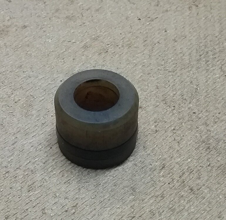
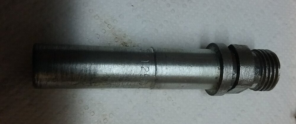
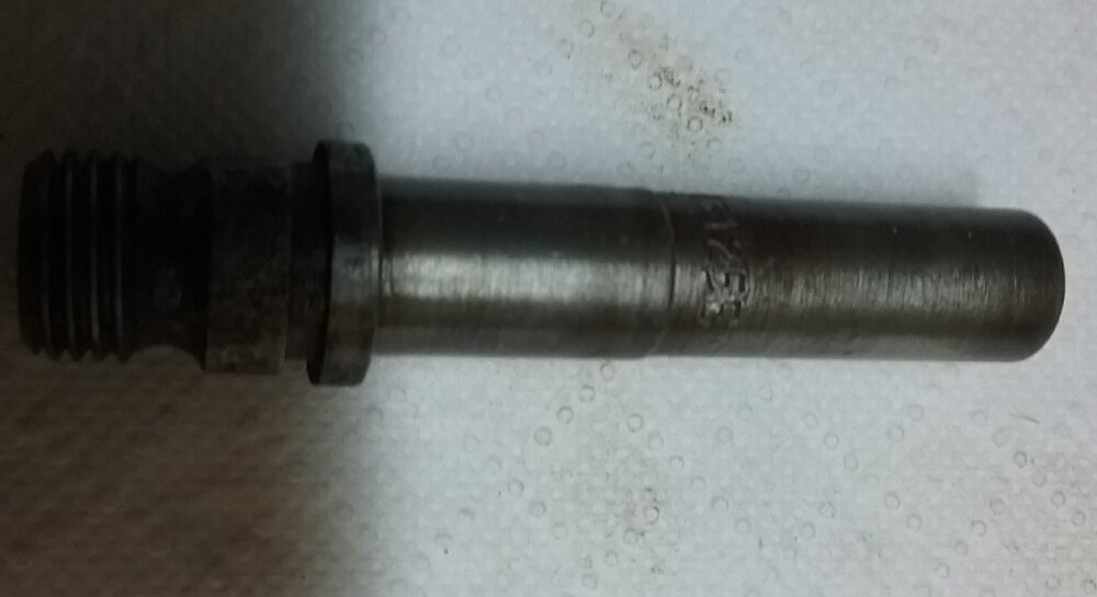
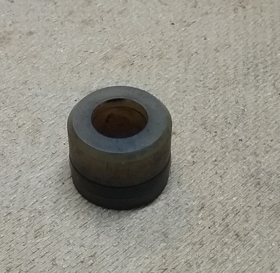
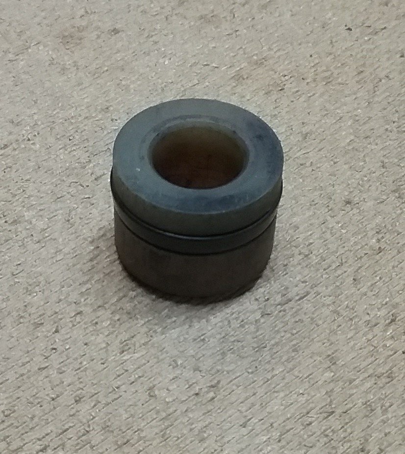
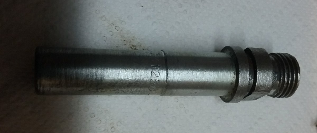
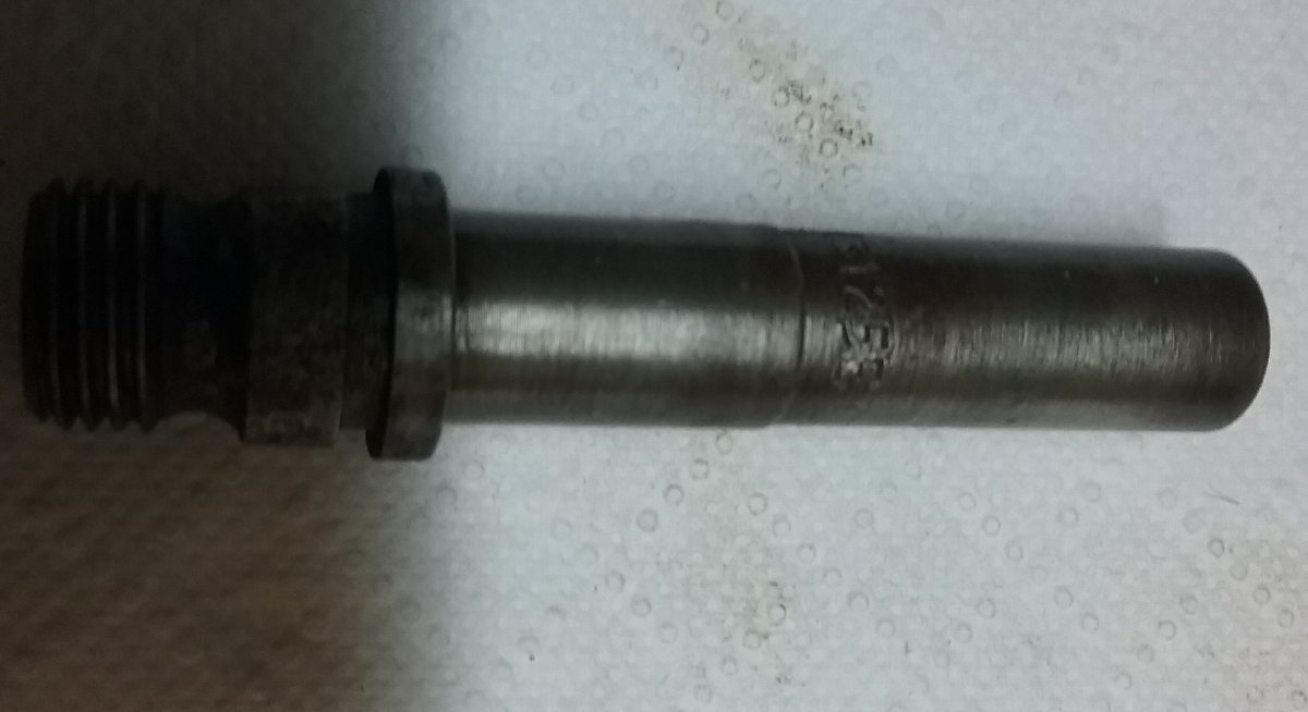
Ok in an attempt to hopefully get an answer I have attached some photos to help.
My issue is that the adaptors I have I cannot find anywhere. Mine are the same as the threaded type but without a thread. Anyone know why and where I can get a replacement.
Also I have 4 injectors that are prefixed with E and 2 injectors prefixed with D. Does anyone know the difference and if it's better to keep them all the same or is mixing not an issue.
Final question what is the reason for the nipple on the end of the poppet cone that makes the spray and is there any difference in spray pattern if it's missing, can see why it should affect it I suspect it could be a cooling device.
Any answers greatly received as always
Thanks Y'all

-
On 3/29/2021 at 5:17 PM, DRD said:
These people are very good: https://www.tayna.co.uk/car-batteries/enduroline/069/
I've just had a battery from Tayna a week ago, they did exactly as on the tin. Really recomend them.
-
Ok thank you all for the replies, really interesting. Couple of points to my earlier posts that may have been missed I think.
I know there are two types of injector adaptors (1 push type with two groves and one screw type with one grove for the o ring) but mine don't look like either
I have 5 adaptors that look like the screw in type (1 grove for o ring) but they do not have a thread and accept my push in type injectors and 1 adaptor that IS a push in type with two grooves.
I would like to make them all the same as the 5 I have but cannot find this type on line, any ideas?? Moss and grimmer do not show this type.
Is there a supplier that supplies good injector o rings together with adaptor o rings. I would like to replace them all asap
Finally I've looked in the manual regarding replacement of the NRV for the MU but is there any tricks to this and who can supply
Thanks for all your help and advice
Steve
-
Thank you Bruce I will see if I can make an adaptor and give that a go.
In looking at the injectors tonight I found that my adaptors are the same as the screw in injector type but without any thread cut into the plastic ( my injectors are push type) has anyone got the same as these. I've looked online for a replacement as no6 adaptor is different and is a two slot push on type and I believe they should all be the same but I can't find adaptors the same as mine for now's 1-5 without a thread, any ideas ?
Also no 4 adaptor is no coming out is there a tool that will enable this one to be pulled out. I will be ordering new o rings for the adaptors as mine are all flat
Thanks
Steve
-
Ok thanks I will give that a go
-
Evening all
Did a search on this but nothing i can find, anyway, took the 6 out yesterday ran like a dream. Took it out again today and for some unknown reason it was running like a tractor. Anyway checked ignition etc and finally found this evening that injectors 1 & 2 are just kind of almost dribbling where as 3 4 5 6 have a nice fine cone. It's almost like 1 & 2 have no fuel being sent to them.
Anyone seen this or can point me to the correct thread so that I can look in the right place as opposed to looking everywhere and possibly finding other work to do lol

Thanks as always
Steve
-
Tim
You can change the flasher unit ( see my previous post as I had the same issue) it's an easy job.
Steve
-
-
Hi All
Tried a search on this but after 14 pages gave up. I have a RHD CP 6 and I need to replace the Tacho cable but there are a number of sizes I see. My inner cable length is roughly 42 inches (old school) and the are cables availanle are from 39 to 48 inches. Can anyone tell me the correct length for my TR6, do I have the wrong one in the first place ?
Thanks to all who reply
-
Ok thank you Michael I will give them a call
Steve
-
Hi Y'all
Hope you are fine and dandy.
Does anyone know if there is an engineering specification for the 6's hardtop front and rear fixings. I have been lucky enough to get hold of a solid original hardtop (which im in the process of getting sprayed) and whilst I do have the side fixings I'm missing the front and rear plus the rubber corner feet ( for want of a better word)
I wouldn't mind having a go at manufacturing them myself but can't find a specification.
I could buy them but have you seen the price !!! For a couple of bolts and spacers etc geezzzzzeeeee
Any help would be grateful
Steve
-
Hi Pete
This is cured if you use a LED relay as directed above and then link the p connection of the relay to the dash indicator lamp(LED). I used the one that Bob gave me the link to. Mine work just fine with no dimming etc
Hope this helps and I suspect will be much easier than trying to put diodes across the switch etc.
Steve
-
Hi Harvey
Long shot but are you sure that the ignition switch is located in the key switch correctly, Mine occasionally comes out and I have to pop it back in
Steve
-
Hi Aarhus
This looks exactly the same as the units I have on my 72 TR6 but the link on shows one view
Happy hunting
Steve

-
Thanks for all the replies chaps
I will take a closer look at the spindles and if they look suspect I may change.
I will see what the balance is like at 1500 John, may point me in the right direction. I will also start with a fag paper gap and start from scratch just in case as I've also noticed that the bleed valve is only just cracked open for 900 rpm which makes me think the butterflies are adjusted too far open.
Steve
-
Hi Stuart
Possibly, but over all three sets ?
I'm wondering if this is just the norm ?
Steve
-
Hi All
Managed to change the coolant and antifreeze today so another job completed.
Whilst I was there I decided to check points timing and throttle balance primarily because I recently purchased a balancing gauge.
All seemed to be good but I've noticed that cylinder 1,3,5 where all reading 2.4 on the gauge and cylinders 2,4,6 reading ~2.0
This didn't make sense to me as I would expect each pair to be the same therefore allowing me to get all throttles the same. Dispite fiddling for some time I cant get them all exactly the same and the throttles can only be adjusted as a pair fro what I can see. Last year I did change the original throttle linkaged for the upgraded versions by Moss or maybe it was Rimmer. Idling is reasonable smooth at 900 rpm and timing 11°
This may have been covered but I cannot find a thread so maybe it's something I've missed.
Any ideas or just a clarification that this is the norm would be appreciated.
Scratching my head
Steve

TR6 Clear Hooters Wiper switch
in TR6 Forum
Posted
Thank you Rob, that is very good solution which I will be trying . You're a wealth of knowledge.
Steve