In the Garage - Spring Edition
Andrew Willmott – TR3a and TR4
Despite the winter holiday and the long running bathroom rebuild I've still managed to sneak a few hours in the garage over the past couple of months.
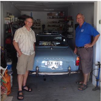
A few of those hours were sneaked while on holiday in South Africa at the garage of Jamie Hart who since I last saw him has sold both his TR3 and TR6 after finishing his long term restoration of a very nice Winchester Blue TR4a which he considers a good compromise between the side screen car and the later six cylinder model. Jamie plans to visit the UK later in the year so I hope to drag him along to one of our events.
Meanwhile back in the UK……
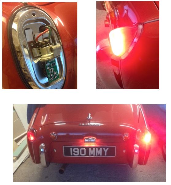
Lebro (Bob on the TR Forum) has been making LED rear light bulb replacements for side screen cars in his spare time and has made them available to "forumites" at a good price. Standard LED bulbs don't suit the early cars as the bulbs hang down from the holder and the main LEDs on the widely available replacements are directed towards the ground when fitted.
The replacements were fitted to the TR3a in a few minutes and deliver a big improvement bringing the visibility levels up to those of a modern car. The pictures below demonstrate the difference.
I was surprised to see that there is a big improvement in the side on visibility as well as the expected improvement from directly behind the car.
Despite the recent debate on LED lighting mine will stay for now as I consider them a major safety improvement.
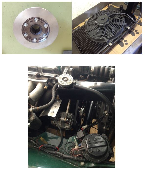
Meanwhile I have finally got around to fitting the narrow belt kit, lightweight alternator and Pacet cooling fan to the TR4.
The solid alloy pulley didn't really want to fit over the original crank hub but a very light skim on the trusty Myford and a slight warming of the pulley resulted in a nice fit.
The nuts fouled on the crank hub lip so a bit of attention with a boring tool relieved the lip enough to allow the flat on the nut to sit against it nicely. Plain washers were fitted on the bolt side, as that was the part turned to tighten the assembly together, the nut being restrained from rotating by the lip on the hub.
This didn't present much of a problem to me but I often find that parts from the major suppliers come with no instructions and need a bit of fettling to make a proper job. I often wonder how the average enthusiast working in a less well-equipped workshop gets around these issues.
The Pacet fan was a second hand ebay bargain and fitted directly onto the lugs already fitted to the radiator shroud by a previous owner.
The lightweight Denso alternator came off a Kubota machine of some sort. A company buys in the new machines and fits additional electrical equipment requiring an uprated alternator. The original alternators from the brand new machines then get sold off.
To mount the alternator a top hat spacer the correct size to line up the belt was machined on the lathe. The alternator is then fitted with a single pivot bolt through the original front mount on the engine plate.
Belt tension adjustment is provided with a perfectly fitting turnbuckle assembly from a Westland Wasp helicopter rotor! I rescued a couple of them from the scrap bin thirty years ago knowing that they would come in useful one day.
The alternator is protected from the heat of the exhaust manifold by a neat stainless steel shield kindly donated by John B who made it for me while he was making one for DRK. Thanks again JB.
The electrical bits required a few mods. The giblets were removed from the control box and some links were soldered under the base enabling the loom to at least look not far from standard. A chunky wire with a 16A fuse in line feeds the relay power terminal from here and a skinny wire (please excuse the technical descriptions used by us electrical bods) runs from a fused ignition feed to the thermostatic switch in the steel tube to the bottom hose and from the other side of the switch back to the relay coil terminal.
Testing proved that the circuit still charges at tick-over and with the fan clicking in at just over a normal 85 deg C (185 deg F) it cools the radiator rapidly before switching off. Traffic queues should no longer present a problem.
Mark Radford – TR6
TR6 Rear Brake / Tail light conversion to LED matrix
Having spent many hours / days on motorways looking at red taillights, I decided it was time to upgrade the dim TR6 lamps with LED replacements. During these boring hours it became apparent that every vehicle uses LEDs to form a pattern. So a plan was hatched to create a matrix of LEDs in the rear red lens, then the options would be unlimited to create a signature pattern.
The result was a 44 LED matrix, which could be wired to create a square for the taillight and all 44 powered up for the brake light. Other options are possible.
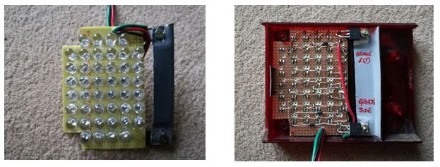
The LED matrix and heat sink fits into the red rear lens and does not require any alterations to the existing lights. Just a small clip holds the circuit board in place. The heat sink sits behind the reflector.
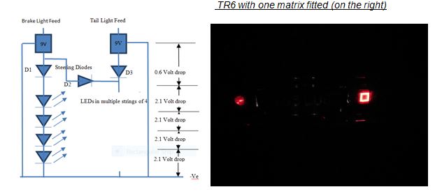
The circuit is very simple and uses two 9-volt DC power supply chips, being fed from the tail and brake light feeds.
The power supply (LM7809) provides a stable 9 volts. Each chain of LEDs is fed via a diode (D1, D2, and D3) to provide the correct voltage for the LEDs and to prevent the tail light lighting all the LEDs (D2).
Referring to the diagram, the 9 volts is distributed between the components, which causes the LEDs to illuminate at maximum brightness and draws 40mA in current.
If required the tail light brightness may be reduced by fitting a resistor between the 9-volt regulator and D3.
Because there are no alterations to the light clusters, I can replace the unit with the original lamps if they fail. It would require the removal of the cluster, which is relatively simple.
The cost was £12 for both sides and it took about 2 hours to build and install per side.
Disclaimer… I am not an electronics designer, so the circuit might break every rule in the book, but it works J
Mark R
John Blake – TR4 x 2
John as just completed a full rebuild of his spare gearbox overdrive unit. The main shaft has been uprated with from help from John Vincent who machined out the bearing housing in the end of the shaft where two needle roller bearings were pressed in to replace the standard single unit. After running the gearbox and overdrive on the bench-test rig John was pleased to find that it runs exceptionally smoothly and quietly.
John has also been improving the throttle mechanism on his twin Webers and writes:
New balance bar link – twice as strong as the last one with no 'flex' in the motion so both carbs are working in complete harmony. I also added a link section with a pair of cap head screws to enable the link section to be rotated 90 degrees disconnecting the carbs from each other and allowing separate carb tuning. The new drop link with rose jointed ends has taken all the slop out of the throttle linkage
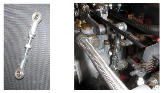
John B
Neat engineering work as usual from John. (ed)
Charles Marten - TR4 V8 Project and TR4
TR4 Woes
The story starts on March 19th on the way to the Sunday Lunch at Broadclyst. A slight misfire started about 5m from Tiverton and became rapidly worse so I stopped in lay-by at bottom of the hill. Checked all leads etc. and all OK so tried again and fired up immediately so started for home up hill and died after about ¼ mile.
Called AA and advised in dangerous position and said I would try to get to next lay-by. Tried engine after about 5 mins and fired right up, so drove to lay-by and it died. AA man came and tried starting; fired up but spluttered and died, so tried usual suspects and thought rotor arm faulty so fitted my spare. Same result. He fitted a spare coil, started up and same result. Swapped dizzy for my spare with condenser & points and tried again with same result. He checked wiring to coil and all OK. Removed top from a float chamber and it was full of fuel. Tried again and fired right up and kept running. He followed me for about 2 miles, stopped in lay-by (I'm loving lay-bys by now) and signed off. Drove to Tesco in Barnstaple, had lunch – very good lasagne – and drove home – NOT!!!!!!!!! The bugger would not fire.
Called AA for a lift home and a young guy came but was pretty useless. Said he would call for a flatbed and I said I would give it one more go. It fired up and ran rough but kept going so I asked AA boy to follow me home, which he did. Left it a short while to sign off AA boy and then started it up and it ticked over nicely – until I sat in it at which point it died. Arrrrrrrrrrrrrrrrrrrghhhhhhhh!!
Fitted a spare coil and it immediately fired up so I parked it in garage. Much head scratching and many local LARGE TR brains came to the only possible conclusion – HT lead from coil to dizzy; there was nothing else it could be.
Some time later….
Fitted spare dizzy cap and leads and it fired right up so drove it out of garage for a spring wash and clean. Started up to drive ¼ mile for MoT but only got 10 yards and it spluttered and died. Engine spins over on hi torque starter motor so removed plugs and drove on starter motor into garage. Finally, found a dark corner and had a good weep!
The next day……
I finally discovered a fuel line blockage caused by sticking float valves by trying to blow through fuel input pipes to float chambers, not as previously from float chamber to jets, which proved to be fine.
Finished putting it back together today and fired it up and it seemed OK, warming up for about 5 minutes before lunch.
Took it for a test run after lunch and all was well for the outward 6 miles, then on way back it started losing power and struggled home thinking that timing slipped.
It had! I had not tightened the clamp properly; soon rectified and running well so fingers crossed for MoT.
Stop press – Now passed MoT.
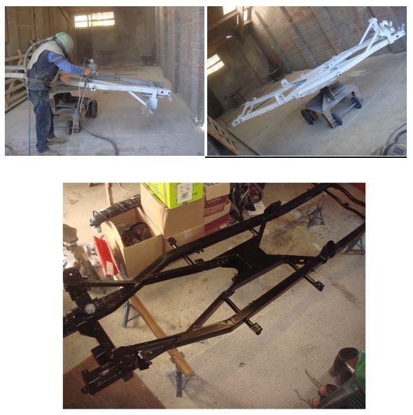
TR4 V8 Joys
Great day today. I borrowed my very good friend's Landie and trailer to take the chassis to Wolfardisworthy – Woolsery to non-locals – for sandblasting followed by zinc spraying. Absolutely brilliant!
The process involves an oxy/acetylene gun similar to a welding torch but with a 4/5mm diameter zinc wire fed into the very hot flame which melts/vaporises the zinc. The zinc is then blown onto the steel by a jet of air resulting in every nook and cranny of the chassis being zinc coated. And all for just £140!!!!!!!!!!!!!
The pristine result was then transported to WM Ironwork for powder coating, ensuring that the chassis is heated before powder coating to prevent air bubbles or pinprick holes. The beautiful black chassis is now available for inspection chez-moi.
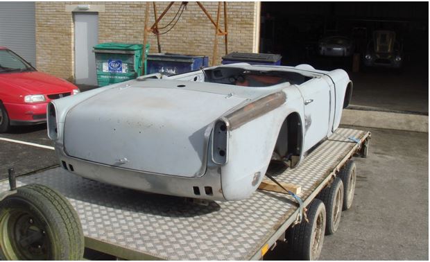
Meanwhile the body has now left NDM and is now at the paint shop being prepared for its gleaming Powder Blue overcoat.
Frank Summers – TR4a and TR7
TR7 failed Mot…….boooo!
It was only a dodgy ball joint so a dead easy fix………raaaaay!
I for one am now looking forward to seeing the TR7 on the road and the Summers family all out together all TR mounted.
Derek Hurford –TR6 and TR7
Derek is pleased to report that his TR7 can no longer be described as a collection of parts flying in close formation:
Having driven the TR7 to get pre mot I noted when decelerating the car seemed to have a mind of its own, I asked him to check it out.
I got a call reporting that the floor pan had separated from outer sills!
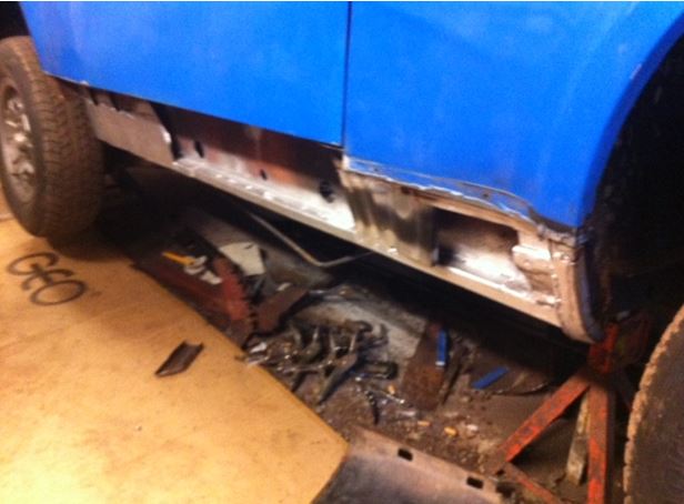
We now have new outer sills and have made some sandwich strengthening panels connected to the inner sills that we found to be in good condition.
Derek
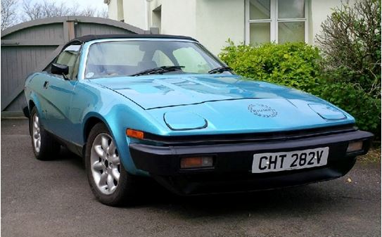
Peter Clark – TR7
Throughout the summer 2016 I had a slight water pump leak on my TR7 but as 150 miles would use only around 300 cc of coolant I decided it could wait until the winter for repair.
This car has only 16000 miles but stood unused in a German lock up for around 20 years. I do not know if it was stored with the cooling system empty or full.
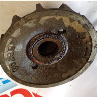
After removing the pump I removed the impeller and as you will see the seal face just crumbled and was clearly only retained by the mechanical seal carbon ring.
Tony Hart, a noted Stag specialist, supplies a new seal kit for £25 or so (plus postage). The kit includes a ceramic seal about the size of a small penny washer and requires a recess to be machined in the impeller in the area of the old seal face to house it.
I liked the idea. I could see that it would retrieve an otherwise scrap impeller and should eliminate the old chestnut of corrosion on the seal face creating a leak.
I have a small lathe so the machining is no problem but any machine shop can easily do this for you. Tony will also do it for you by post.
After machining, the ceramic seal is bedded into the recess using silicone sealer.
The job has now been completed and is leak free.
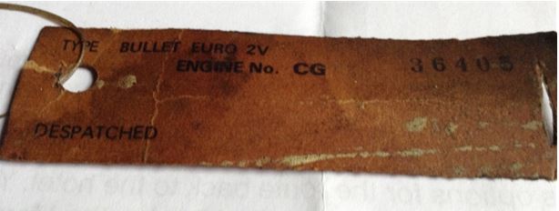
As an aside I found the ID tag shown in the photo attached to the breather pipe of the rear carburettor and thought it would be of interest, particularly as the code name Bullet has been retained right up until 1981 when this car was built.
I hope this is of interest and thanks to the contributors in January for the most interesting reading.
Peter Clark
Paul Gibson – TR6
Doesn't everyone remove the engine to detail the bulkhead?
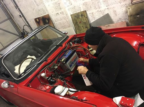
Paul's new engine is now fitted and has a few miles on it and I can report that it sounds really nice with a slight growl from the exhaust as it picks up its skirts.
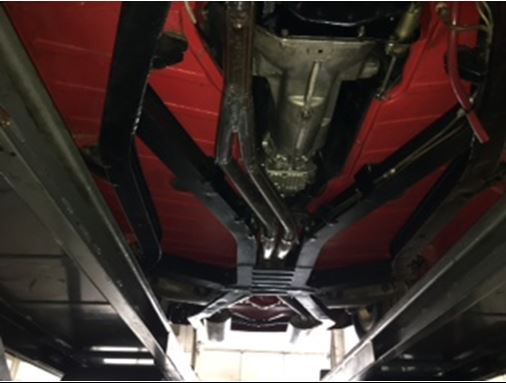
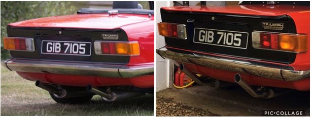
Paul has fabricated a nice Y piece to mate the new manifold to the original system, the silencers are now usefully further from the ground and feature subtle changes to the tailpipes.
Keen eyed observers will also notice a little known performance modification next time they see the car……..red seatbelts!
Dennis Hobbs – TR5
Thanks to Dennis for the following article aimed at the more technically minded among us. It's ok, there won't be a test.
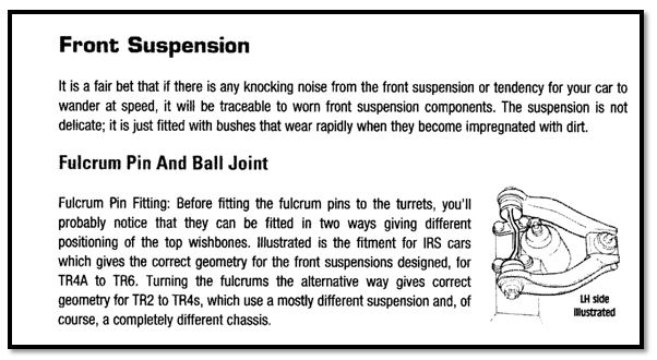
The reason for this article stems from my own experience of conflicting information regarding the fitment of the upper Fulcrum arm on my TR5
Dennis Hobbs 03/03/2017
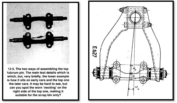
Some 12 years ago now I carried out a full restoration of my TR5 that I have owned from 1973. The restoration included the chassis being repaired and set up by CTM. When rebuilding the suspension I used the original blue workshop manual by Triumph for reference. I was aware of the change of steering geometry between earlier none IRS cars and the TR4A, TR5 and TR6 IRS cars, so I fitted my fulcrum arms as per the technical drawing in the relevant manual. You can see it shows the later IRS 3deg rear offset upper wishbone arms, the longer shaped arm to the front. I have measured the offset on the fulcrum pin showing on this drawing it is 2mm, it clearly shows what I wrongly assumed, to be the correct fitment of the fulcrum pin. I was to be enlightened much later.
My second reference was the book I purchased through the TR Register shop. 'How To Restore Triumph TR5/250 & TR6'.
Page 125 indicates that the Triumph manual is correct. One would assume that you are viewing the picture from the right hand side of the car.
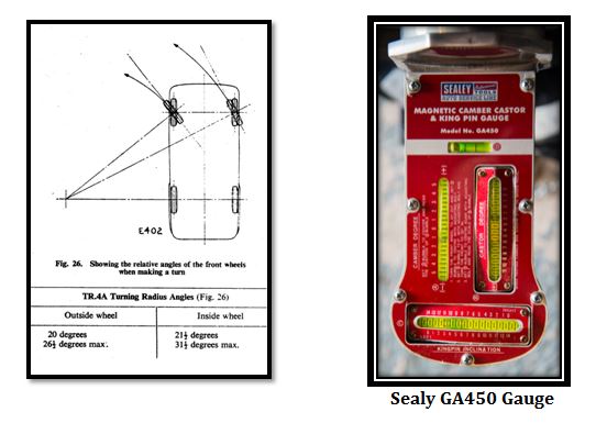
I have over the years revisited the fitment of this part on many occasions, as I was not happy with start line stability. On a number of occasions I reset the shims on the lower wishbone arms, adjusting camber and caster but was never happy with the king pin inclination (KPI) as it was off the scale on my gauges. I had assumed my gauge was faulty. Read on below.
Above is a scan of page 115 of the Moss-Europe TR5-6 parts catalogue March 2011. It was after seeing this referenced on the forum that I revisited my suspension. My first stop was to take my car to a tyre specialist with computerised geometry equipment. The readings confirmed that there was no fault with my Sealey GA450 Camber, Caster and King Pin Inclination gauge. The readings for my KPI were +18 deg 59 minutes left side and +18 deg 20 minutes which would result in experiencing straight line instability. Overalls on with jack and axle stands ready, I first did a full geometry check front and rear and noted the readings, then with both front wheels off, I started by stripping both top fulcrums and arms out, one at a time checking for wear on the bushes. Then reversed the fulcrum pins to the correct orientation, refitting the longer more shaped one of the suspension arms to the front to maintain the 3 deg off set to the rear of the car, this is related to the caster angle. A tip for anybody carrying out this work, Note that the inner set screws holding the fulcrum pin are shorter in order to clear the inner wing.
After refitting I reset the lower shims to 2 shims on the 4 points of lower wishbone arms, set the tracking and Toe-out on turns then drove the car around the block to settle the suspension in.
On completing a second full geometry check, all my readings were found to be acceptable considering the vehicles ride height. I reset the camber on the rear wheels with the adjustable brackets available from CTM which were fitted earlier last year. When I fitted shorter springs I sorted the 1,2 & 3 notch rear suspension swinging arm mounts to give the right ride height with my lowered springs, so the adjustable brackets were only required on the outer pivot points.
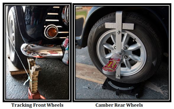
For the tracking I use two pieces of string tied round the rear over riders tensioned forward to the front wheels tied to two axle stands so the string is in contact with the tyres in a centre horizontal position, you then check the contact on the front tyres, zero toe is when you have equal contact front & rear of the front tyres.
Steering Geometry Explained Triumph TR4A, TR5, TR6, IRS Derivatives
There are four main measurements which need to be assessed, considered and adjusted if required to suit your own requirements and considering any modifications and intended use of the vehicle. i.e. Standard, Lowered suspension, Fast Road Car, Track Days.
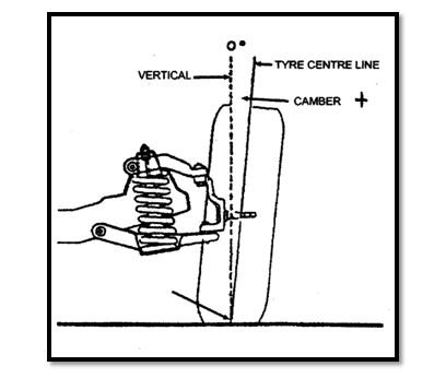
Measuring Camber Angle.
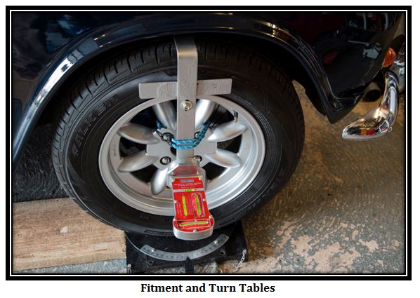
Camber angle is measured by driving the vehicle forwards on to turntables before centralising the wheels and attaching the appropriate measuring gauge. I have used my Sealey GA450 magnetic Camber, Caster, KPI gauge attached to my homemade wheel clamp tool. You then set D bubble to the centre position and read off the camber part of the gauge.
Now check your rear wheel camber. When adjusting replace the turntables under the wheels, block front wheels and release hand brake.
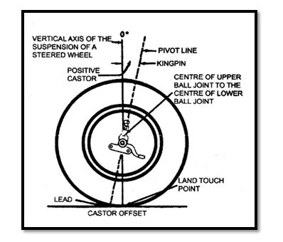
Measuring Castor Angle.
Castor angle is measured with the front wheels still on the turntables. The foot brake pedal must be held down to keep the brakes applied; I made up my own tool for this. Turn the front wheel 20deg out, set D bubble to the centre position. Set B bubble to zero with the adjusting screw under the gauge, turn the wheel in 20deg, reset D bubble to centre and read off the B scale bubble.
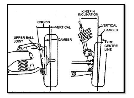
Measuring Kingpin Inclination.
KPI angle is measured with the front wheels still on the turntables. The foot brake must be applied again for this measurement
Turn the front wheel out 20deg set D bubble to the centre position, set C bubble to zero for the appropriate wheel "Right or Left" with the adjusting screw under the gauge, now turn the wheel in 20deg and read of the C scale bubble.
Measuring Track & Toe-out on Turns.
Toe-out on turns, you measure this with the turntables. The readings being taken from the degree scales on each turntable. As you can see by the diagram the inner wheel turns a tighter turn than the outer wheel. If this is incorrect the tyres will scrub when turning. You can see that there is a one and a half degree difference regarding the circumference the wheel is turning, also a maximum turn deg for each wheel, this will change on left to right lock.
The important measurement to get right when setting track toe-in and toe-out on turns is make sure your steering rack is in the centre position before any adjustments are made i.e. number of turns lock to lock and centre the wheel then hold that position, also when adjusting the track rods they need to be equal lengths. You can centralize your steering wheel by removing it and setting to straight ahead as the last job.
Dennis
It was nice to see Dennis's repainted wheels on the Drive It Day. They are now a fetching shade of graphite and to my mind change the look of the car considerably giving it a meaner more purposeful look. (Ed)
Steve Williams - TR5 (…and a BSA)
Steve's TR5 has seen a bit of fettling ready for a busy summer. Those who care to crawl underneath will see shiny new drive shafts, which unlike his old ones make no knocking noises at all.
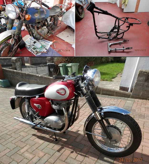
As his car doesn't seem to require a lot of attention Steve has been lavishing his attentions on a BSA motorcycle.
It had seen rather too many years parked under a hedge being used to cultivate moss but as can be seen on the accompanying photos it is now something that Steve can be proud of and just needs a few miles under its belt to get everything settled down nicely.
For Sale and Wanted: email you're for sale and wanted adverts for inclusion in the next issue.
Wanted
TR4 Rear over-rider stays (between the rear of the chassis and the rear over-rider)
andrewawillmott@gmail.com
For Sale:
TR6 1971 car has just come on the market, location Devon. It's Peter Stewart's, a very tidy and high spec car.
If interested to view contact Dennis 01404 81166 or by email dennistr5@icloud.com for photos and any relevant details.