

paul83
-
Content Count
164 -
Joined
-
Last visited
Content Type
Profiles
Forums
Calendar
Posts posted by paul83
-
-
Hi All,
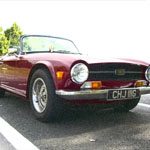
I am in the process of converting my TR6 from LHS US spec to UK RHD, and discovering a world of difference in the wiring!
After hours of searching, I need help on the switches used for the lights if the car does not have a foot-operated dip switch for the headlights. Where is/are the light switch(es) located in the car, and what are the positions of the switch(es) to enable off, dipped beam, full beam and flash (of the full beam)?
Thank you,
Paul
-
Thanks for posting Toby.
-
+1 for Tracy Tools - excellent quality tools and great service.
-
Hi,
To finish off the holes in the body where the bumpers mounted, I used bolts with countersunk washers (bolted to the original brackets coming off the chassis). It gave the smallest profile / least flashy look (which is what I was looking for).
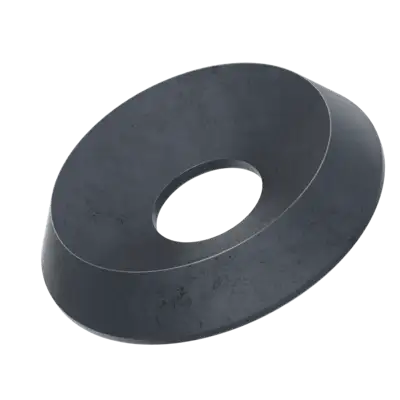
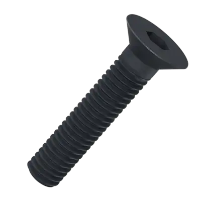
Originally I used aluminium bolts and washers, but found that I could not tighten them up enough. As a result, the body moved, the holes got bigger and the paintwork took a hammering. This time round I am using A4 stainless steel bolts and countersunk washers, with a rubber washer either side of the body panel. This gives as tight a clamping action as with the bumpers on.
It took ages to find the right bolts and countersunk washers. I found the UK supplier ACCU, but they are not cheap, and it takes times as they are made elsewhere... https://www.accu.co.uk/solid-countersunk-washers/409607-HKW-M12-A4-BL
Paul
-
Thank you all for the pics.
I've discovered that John Skinner in the UK does a non-sewn leather cover for the dash pad. (https://john-skinner.co.uk/model/tr6/)
Peter, your stitched looks very well made.
Paul
-
On 9/25/2023 at 11:38 AM, mleadbeater said:
do they have to be sewn ?
youtube shows a guy covering dashes with many contours with hide, bit by bit.
I was considering doing this myself, with black hide, its very stretchy.
Just a thought
Mike
Hi Mike,
I think that is what I am aiming for: a non-sewn, leather version of the original. I suspect it is not possible!
Paul
-
Hi All,
Please could someone post a picture of their TR6 with leather dash top and crash pads? I am trying to determine if it looks similar to the original but more plush, or if it looks completely different. I know each to their own preference, so I am not asking which is better.
Thanks,
Paul
-
3 hours ago, DIYBOSSCAT said:
Mike,
this what I did when I had my wings off for repair. I used a empty silicon tube, cut down, and cut a good bit of the nozzle off and 12mm rubber tube. It exits through a grommet on the splash guard.
Vince.
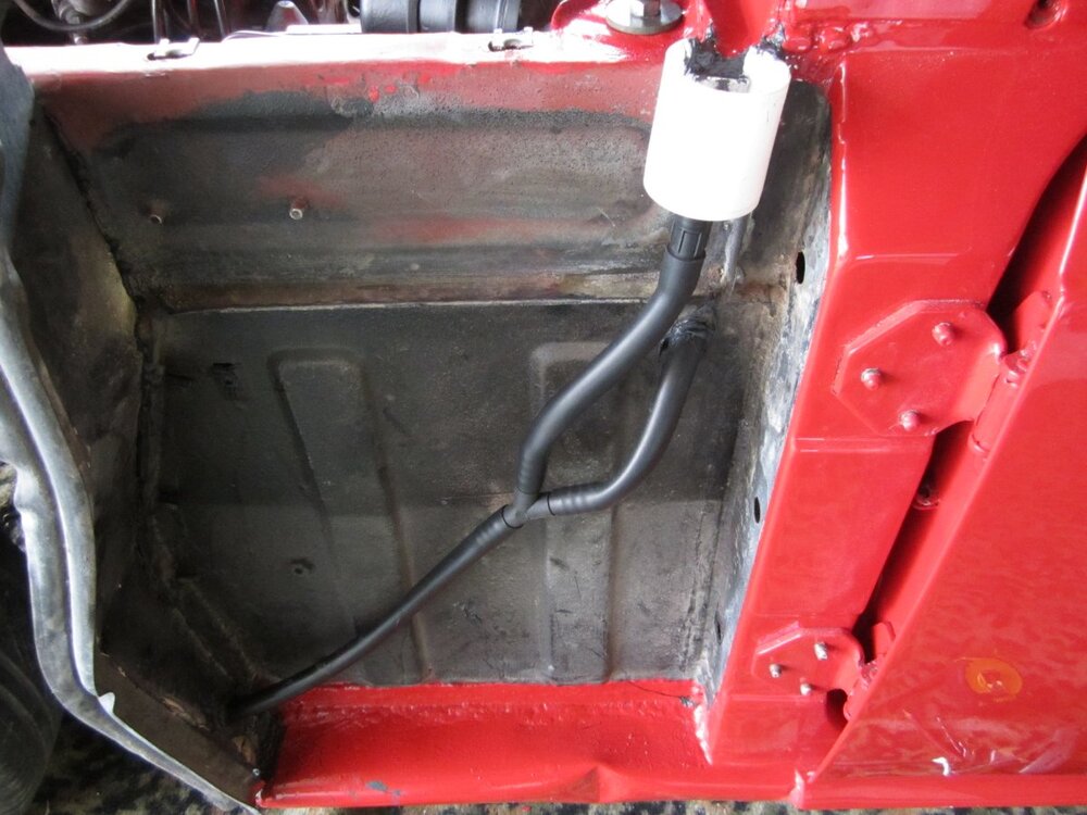
Thanks for posting Vince.
-
Here's a summary with metric included
Injector, length (imperial|), length (mm), fitting at metering unit
1 30 & 1/4" 768 Right angle
2 31” 787 Banjo
3 30” 762 Right angle
4 29 & 1/8” 740 Right angle
5 21 & 3/4" 552 Banjo
6 20 & 1/4" 514 Right angle
total 161 & 3/8” 4,123
-
23 minutes ago, saffrontr said:
Paul,
The lengths are in the TR6 parts book. pipe 1 is 30 & 1/4" long, pipe 2 is 31" long, pipe 3 is 30" long, pipe 4 is 29 & 1/8" long, pipe 5 is 21 & 3/4" long and pipe 6 is 20 & 1/4" long. You'll have to convert to metric yourself. They are listed on pages 63 & 64 of the May 1973 parts book and no doubt others.
cheers
Derek
Thank you Derek.
I didn't even know there was a dedicated parts book!
Paul
-
Hi Phil,
The general view is that the standard system of cross box, and twin pipes into it the box, is good for a standard engine and standard exhaust manifold. Standard steel or stainless steel give the same performance but the latter lasts longer (and is more shiny!).
As Gareth said, the single system is a different (larger) bore than the twin system.
Changing the exhaust to a larger bore without changing the manifold and engine performance (cam, pistons, ignition, tuning) will not give you any performance benefit. Conversely, the impact of improving the engine and manifold will be much reduced if you keep the standard exhaust. The list of things to do to the engine for noticeably increased performance is expensively long!
I know that in the USA custom exhausts are much more common and much less expensive, and so people often choose an exhaust based on looks alone.
Paul
-
Hi All,
Does anyone know the lengths of each injector pipe (between metering unit and injector at manifold)? I am converting from carbs and have no reference, and can't find the information in the Brown Book nor the Forum.
Thanks,
Paul
-
Thank you Roger!
-
Hi All,
Two questions about the wheel cylinder in the rear break:
1. Positioning
The rectangular opening in the back plate is much wider than the space required for the wheel cylinder and hand break level to operate. Should I position the wheel cylinder so that is it in the centre of the back plate, directly above & in line with the break adjuster at the bottom?
2. Movement
I have refurbished the wheel cylinder and back plate, and am using new retaining clips to secure the cylinder to the back plate. On one of the back plates, the wheel cylinder can move horizontally without much of a push - it will easily move when using the break-lines to operate the wheel cylinder. Should this be fixed so as not to move?
Thanks,
Paul
-
Hi Peter,
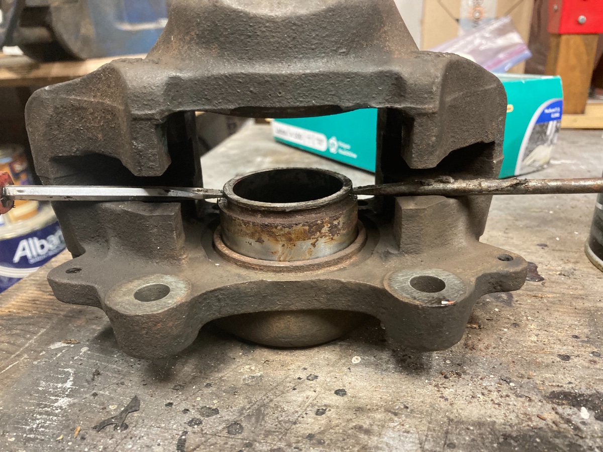
If you are able/ willing to remove the callipers from the car, then this can be done by mechanically leavening out the pistons:
- Ensure either the bleed nipple or break pipe entry is open (to allow flow of fluid / stop suction due to non-flow of break fluid).
- Remove the dust cover from the piston.
- Spray WD40 between the side of the piston and the housing (if the piston has rusted and has not been used for a while, it might be stuck).
- Gently push the piston back into the calliper - just a little bit, to free the piston.
-
Using two flat screwdrivers on opposing sides, lever the piston out. Use the protrusion on each side of the calliper as the fulcrum point for the screwdriver, and insert the screwdriver into the recess in the piston used to retain the dust cover.
Using just one screwdriver does not work because the piston tilts within the housing and locks.
See the attached photo.
I have used this technique on rusted pistons and managed to extract them without damaging them.
@anyone: does anyone know if stainless steel pistons are a good thing? Stainless steel expands about 34% more than carbon steel (of the standard pistons), so I was wondering how they behave once the disc has become hot due to breaking.
Paul

-
Hi Adrian,
The short answer is that I don't know...
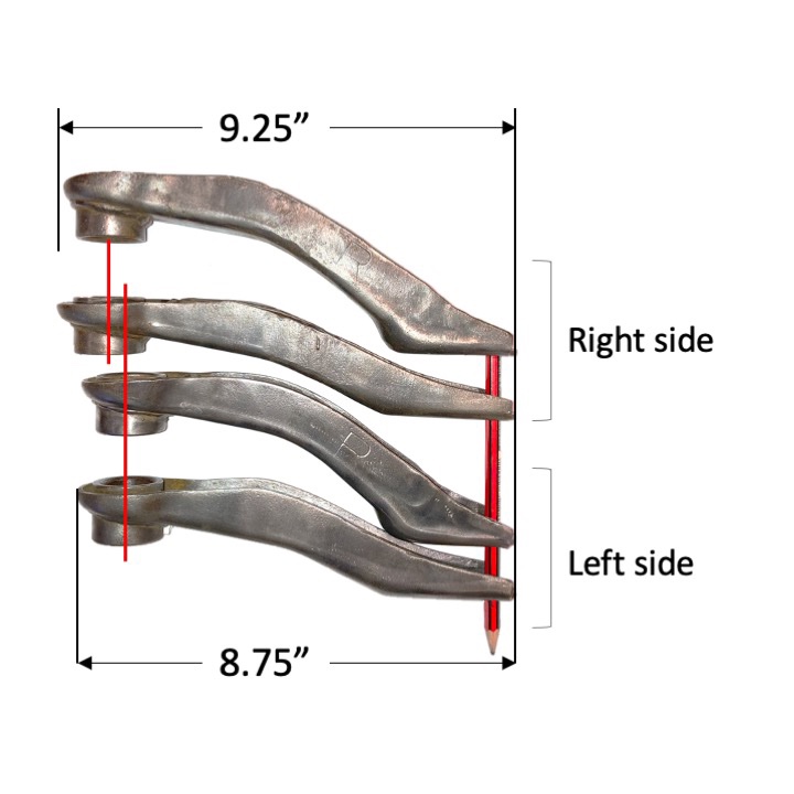
I raised the issue on the Forum here: TR6 Forum: different-upper-wishbone-arm-lengths, which suggests that the shorter pair are TR4. The general consensus is that TR4A - 6 use the same (longer) wishbones, and the TR4 (not A) uses the short.
However I cannot confirm this because I cannot find the specification length of the wishbones in the TR6 Brown Book or anywhere else. An addition, I purchased new upper wishbones (for the TR6) from Moss and they are shorter than the long pair I had, and the same dimensions as the short pair. Moss could have sent me the wrong pair.
So I am in the process of installing the shorter wishbones. I suspect that as long as both sides match, the only issue is the camber angle.
Whilst rebuilding the suspension, I discovered something that you might also want to check: on my car, one of the rear mounting plates, which is welded to the chassis behind the turret and where the lower wishbone bracket is bolted to, is out of line with the front plate (and out of line with the front and rear plates on the other side of the car). It has obviously collapsed/ been bent at some point in the car's life and then someone has welded on new plates either side to add strength. But in adding the strengthening, the plate has been fixed out of position. The upshot is that this particular plate/ bracket needs extra shims to align the lower wishbones. The rear has four shims and the front has 2 shims, and the wish bones marry up in the same was as the other side of the car which is straight.
Nothing is ever straightforward!
Paul
-
Hi Adrian,
Not sure if you have checked... Are the upper wishbones/arms the same length on each side of the car?
I am currently doing a body-off restoration of a US TR6 and I found the wishbones on the left to be longer than on the right hand side. Either the length of the TR6 wishbones changed sone time during production or one set is from a different model (they look identical and have the L/R marking so presumably are both Triumph). The difference in length, from centre of bush on fulcrum to centre of ball joint in vertical link, is about 3/4", which creates a huge difference in camber for the same shims.
Paul
-
Hi All,
Many thanks for your replies. I knew they should be the same(!) - but sometimes with our cars you just don't know...
The chassis is straight and in very good condition. Which suggests that it is not original, so maybe accident damage, bodged arms to counter, then new chassis. When I took the car apart, there were shims galore!
Thanks for the measurement - I couldn't find any in the TR6 Brown Book. And thanks for the observation re Moss catalogue.
The shorter arms are indeed 7 11/32" between the centre of the large bush to the centre of the outer bolt hole, so we know where they were pinched from.
Paul
-
The bit I struggled with was putting in the pin that locks the door handle in place. A pair of long locking pliers turned the job from nightmare to relatively easy:
-
Hi All,
Whilst refurbishing the suspension components of my 1969 TR6, I have discovered that the left hand side upper wishbone arms are shorter than the right (see attached photo). (The bottom arms are the same length on both sides).
1. Is this right?
2. If not, what are the correct arms for the 1969 TR6?
As an aside, someone has box welded the right hand side arms, presumably to strengthen them. Is this necessary?
Thank you,
Paul
-
Hi Len,
Thank you for the offer. A completed car is what I am looking for! And Culverstone is not too far.
Could I come round this Friday, or the weekend at a time that suits?
Paul
-
Hi All,
I am in the midst of a body-off restoration of my 1969 TR6. I am converting it to Right Hand Drive and am having difficulty finding measurements (for example, how far over the pedal box goes) and where to place things (such as the engine bay pipe work).
I live in east Kent. Is anyone willing for me to visit them and crawl over the engine bay with tape measure and camera?
Thanks,
Paul
-
Thank you all for your comments, guidance and questions. Really very helpful. It is so good to not be alone in my restoration!
I hadn't thought of the possibility of a long bonnet - it certainly could be given the car's US heritage. Over the years of my ownership, I have corrected several US-style 'alteration's and bodge jobs...
The chassis is earmarked for a complete renovation by a TR professional - it is not in the straightest of condition.
Thank you for the photos and the measurements - always invaluable.
-
Hi,
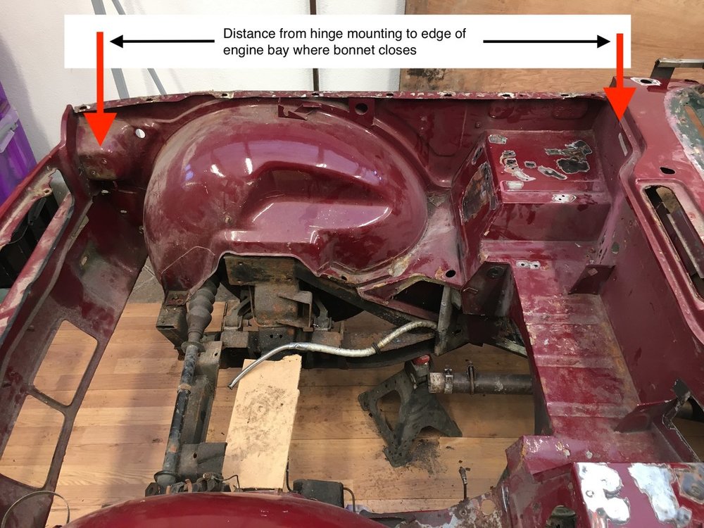
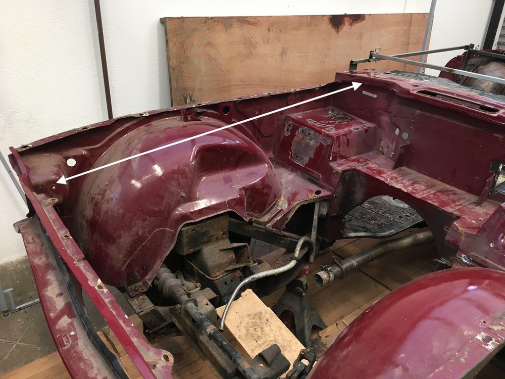
Can anyone suggest how I can adjust the distance between the engine bay firewall and the mountings for the bonnet hinges? And also, what that distance should be?
My TR6 has been in at least 2 front end crunches. As a result, the bonnet is pushed right up against the edge of the engine bay parallel to the windscreen, even though the hinges are bolted as far forward as possible (with widened holes in the hinges to give even more room). It seems that the length of the inner front panels, from firewall to front grille, has been compressed - by almost as much as 1 inch.
The car is currently disassembled for a body-off restoration (and conversion to RHS).
Thank you,
Paul


Headlight switch set up without the foot-operated dip switch?
in TR6 Forum
Posted
Hi Tim & Miles, thanks for your help. An additional stalk seems to be the way to go.
Question: did any of the TR6 models not have the foo-operated dip switch?