


Colin Fairhurst
-
Content Count
215 -
Joined
-
Last visited
Content Type
Profiles
Forums
Calendar
Posts posted by Colin Fairhurst
-
-
1 hour ago, r-fox said:
I'd take a LUCAS Sports coil DLB 105, Moss nr. TT2981, 3 ohms ,40000 volts.
You will be happy with.
When using a 1,5 ohms coil you need a ballast resistor also same 1,5 ohms , this must be bypassed by a relay while starting the engine.
Thus you get higher voltage to the coil's primary circuit which provides high voltage at the lead to the distributor then and that helps better engine starting ( improved igniting energy) under severe conditions ( e.g. in wintertime).
Right after release of the start button the ballast must be again connected in series with the coil, thus 3 0hms again system voltage.
hope this is of help
Wolfgang
I do understand all that but what about the effect of the voltage on the module, that is, 12Volt standard coil or 6 to 8 Volt ballasted coil?
I have read that there are different types of Lumenition Modules and that some are designed to operate at less than 12 Volts.
-
19 minutes ago, RobH said:
If it states not less than 3 Ohms then I would take that as definitive Colin. Since the TR2 has no mechanism for switching a ballast resistor anyway, why not just go with that?
Of course, you could use a lower resistance coil as long as the ballast resistor is always in circuit so the total is always 3 Ohms or greater, and perhaps that is what the diagram is showing. There is no benefit in doing that but it might be shown for those cars which have ballasted systems as standard.
Thanks for that Rob. Do I take it that the 1.5 ohm coil and the 1.5 ohm resister add up to a total 3 ohms for the Lumenition module?
It would be relatively easy to connect a ballast resister in series with the 1.5 ohm coil and a separate 12 Volt to the Lumenition module from the ignition.
I was also thinking about the Voltage. A standard coil would have 12 Volts approx. all the time and the ballast resisted coil would be at 7 to 9 Volts when the engine is running.
Regards, Colin
-
I have a Lumenition PMA50 Optronic kit which I plan to fit to my TR2. I have fitted several Lumenition kits to my classics over the years and in fact my wife's Spitfire 1500 has had one fitted since the 1990s.
My problem is that the instructions state 'Suitable for coils or coil/ballast combinations of not less than 3 ohms and also states:-
'Not suitable for low resistance (i.e. less than 1 ohm) electronic ignition coils.
It then shows a diagram with a coil and ballast resister included. These coils which have ballast resisters are usually 1.5 ohms.
Although I am reasonably competent with car electrics I find this somewhat confusing and slightly contradictory.
Can anyone help please?
Regards, Colin
-
Just swop the spring that operates the diaphragm with the one from the old pump
-
The Moss parts list shows that the part numbers for the TR6 Crown Wheel & Pinion and the Diff. bearings are the same as those for the TR2 & TR3 with the 3.7:1 ratio.
Does Logic say that the setting up dimensions are also the same ?
Regards Colin
-
The part numbers for the 3.7:1 Crown Wheel & Pinion on the TR6 are the same as those for the TR2 and TR3.
Same applies to the Diff. bearings.
Does logic imply that the dimensions for setting them up are the same ?
Regards, Colin
I intended to post this on the TR6 forum where someone is asking for Diff. dimensions
-
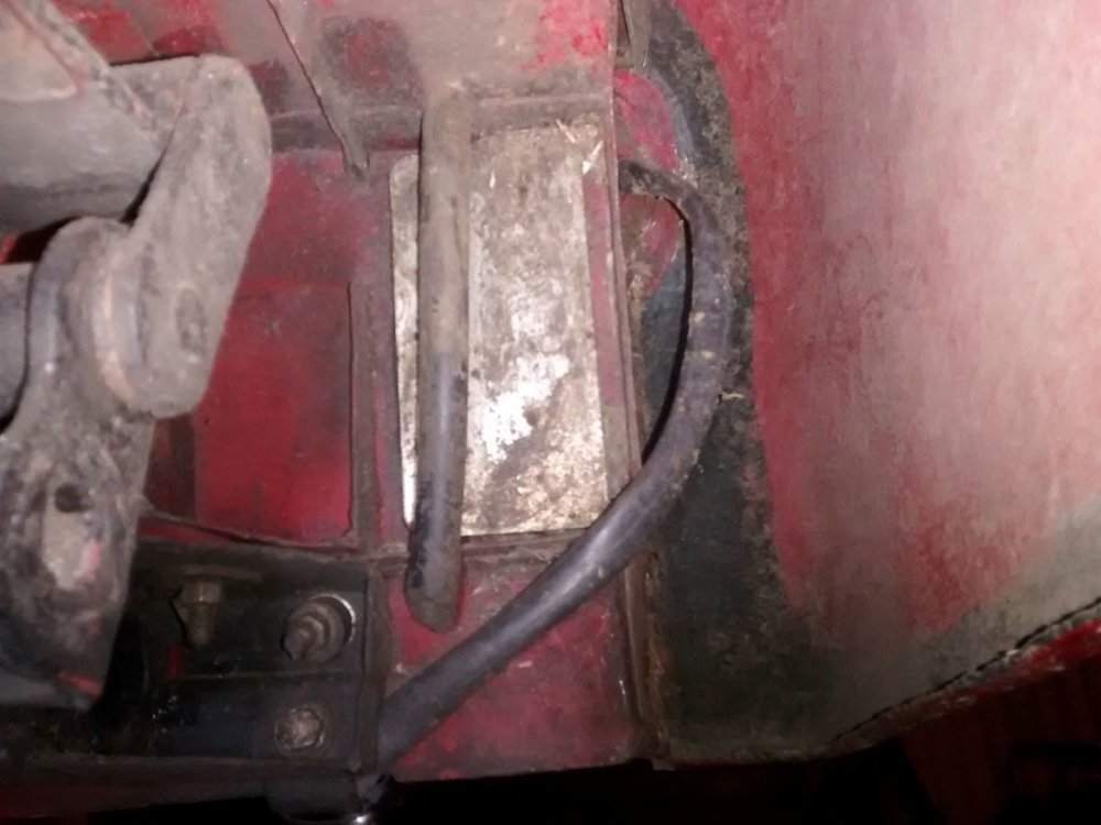
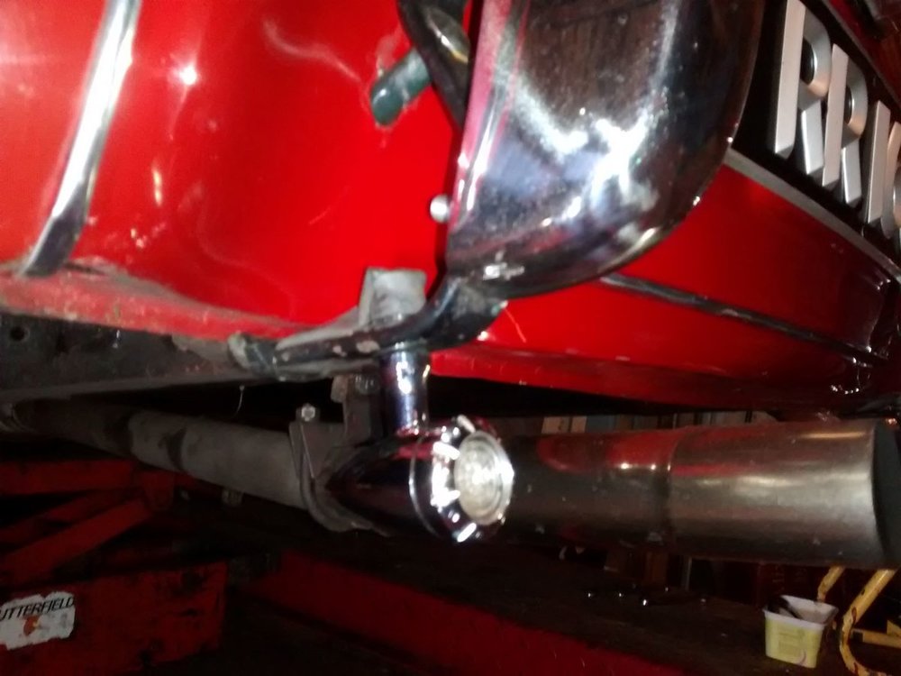
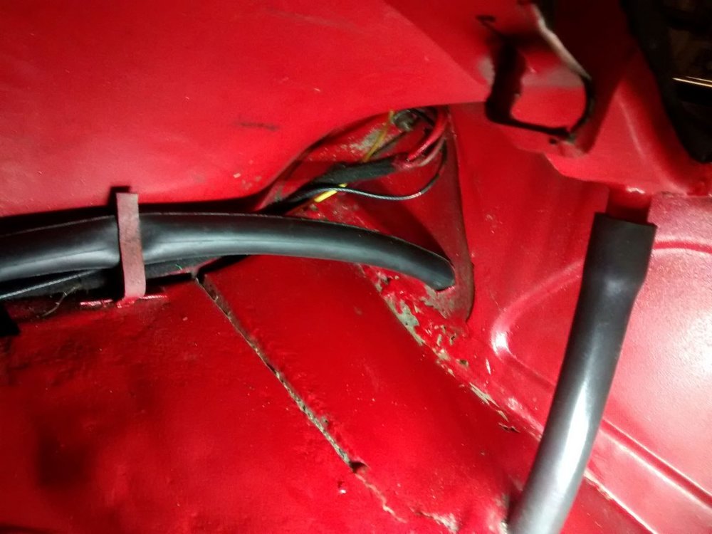
Hi Phil,
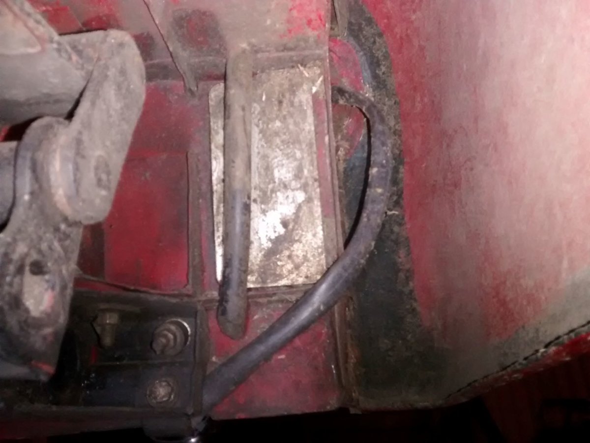
I fitted two LED lights to the rear of my TR2 ( see pics.). They have three functions i.e., daytime red running lights, red brake lights and orange indicator lights. There are four wires which I passed through a length of bicycle innertube and up inside the rear wing to holes which were already there into the boot. I had already fitted an extra wire from under the dash to the boot when I rebuilt the car 12/13 years ago. I used this wire as a switched live from the ignition for the running lights. The other wires were connected to the relevant wires already in the boot.
From what you have said I assume you have already fitted the extra wires from switches in the cabin to the boot.
-
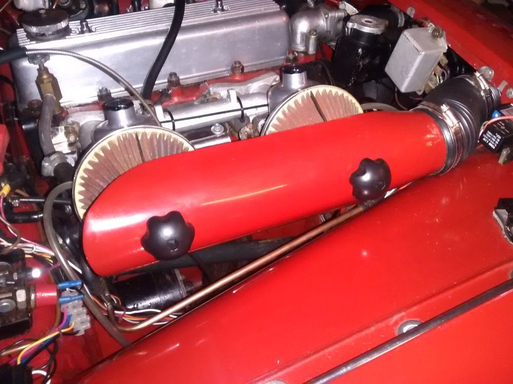
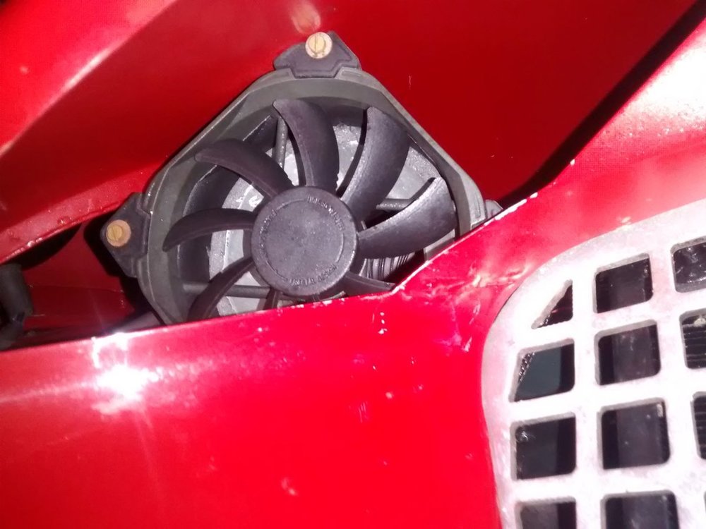
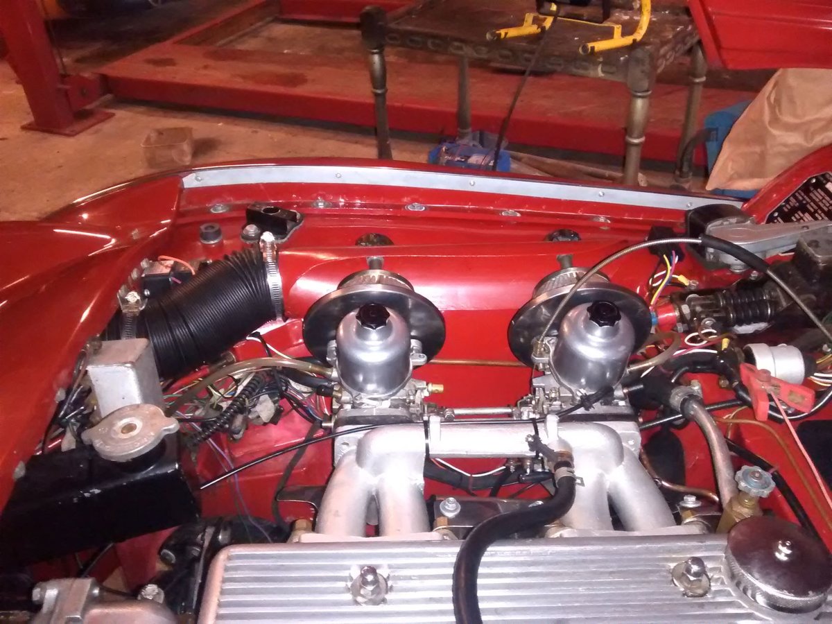
This is my effort ( see pics). I have found that the computer cabinet cooling fan to have very little effect.
I have ordered an Attwood fan.
Regards, Colin

-
Thanks Bob and Ben. That fan looks interesting. The air flow-rate and the amps rate are impressive. I will check measurements and will probably order one. I may even consider the larger size one.
Regards, Colin
-
9 hours ago, Ben Freer said:
My solution wasn't my idea but I got an inline fan from Merlin Motorsport. It's original purpose is to ventilate boat bilges. Hence it is known as the "bilge pump". It's made of plastic and isn't particularly pretty but could be painted to help it blend in. When I was at Merlin I was intending to purchase a far more expensive, metal model made by a well known electric radiator fan manufacturer. However the "huff" - technical term - was far better from the cheap plastic one. It's mounted behind the grill with a piece of ducting up to the carbs. I only switch it on in traffic queues and it makes the car far less grumpy.
Hi Ben,
Can you tell me what size and make of fan you used.
Regards, Colin
-
9 hours ago, Lebro said:
+1 for Ian's explanation above, I have adopted the fix suggested by Ben Freer, which is to insert an in-line axial fan into the fresh air tube. Mine switches on with the main cooling fan, so providing cool (outside) air to the carbs while stationary. Roger H has the same arrangement.
Bob.
Hi Bob,
Can you tell me which fan you used.
I have fitted a 120mm 12 Volt computer cabinet cooling fan under the front panel just above the radiator with a duct leading to the carburettors and with a switch under the dash.
The problem is that when I switch it on the air flow-rate is very poor and doesn't seem to have any effect. The spec. for the fan states 84 cubic feet per sec. It is possible that the computer motherboard which the fan would normally be plugged into would have better control.
Regards, Colin
-
When I Waxoiled my Tr2/3 chassis I found that I could pass a thick wire from the rear end right through to the front end. There are cross-tubes at various points but they don't form a complete blockage.
At the time the chassis was completely bare so I could elevate the rear end and using a purpose made funnel I could pour hot Waxoil down the chassis rails until it came out of the holes at the front then flip the chassis over, drop the rear end, elevate the front end and collect the surplus waxoil as it poured out at the rear.
There are various small holes in the sides of the chassis that need to covered with masking tape.
Hope that helps.
Regards, Colin
-
I purchased brake shoe linings for my Triumph Roadster which were listed on eBay @ £64.50 per axle set and were also listed for the Land Rover series 2 @ £12.99 per axle set. Both incl. rivets and shipping.
Exactly the same, in the same box and with the same stock/part number on the box and are exactly the same parts.
No prizes for guessing which I did purchase.
I have found this to be the case with a number of parts for vehicles depending on the model. Back in the 1970s I had a Audi Coupe S which was a much more expensive coupe version of the Audi 100 saloon. The dealerships had different part numbers for the same parts for each model and the coupe parts listed cost four times as much as the saloon for the same part.
Again, no prizes.
Regards. Colin
-
It could be that the engine is off a later TR model which used H6 carbs or HS6 carbs
Regards, Colin
-
Hi Richard,
I have found in the past that the outer column tube is soft soldered into the steering box which perhaps explains why this has happened.
Early last year I had a head on collision with the Armco (TR2) causing extensive frontal damage including the same problem as yours with the steering.
I found that the drop arm from the underside of the steering box was out of alignment and after removing the steering column and dismantling the box I found that the rocker shaft which carries the peg had been twisted within its length by at least 10 deg. which reinforces Bobs comments regarding checking everything out.
Fortunately I have a very good spare column.
Regards, Colin
-
I have recently been told by a good authority that wheel locknuts should not be loosened or tightened by using an impact tool.
The lock nuts are not strong enough and can shear off leaving a rounded head.
Regards, Colin
-
Hi Dave,
I can strongly recommend "Ken & Lyn Paints". Phone 07778165966.
Although I have not actually met Ken I know that he has had many years of experience and is very willing to pas on his knowledge.
Regards, Colin
-
18 minutes ago, RobH said:
Yes 5 psi is certainly a bit too much for SUs and a quick web search shows several instances of people complaining of the same thing. If it was a new pump perhaps you should let whoever supplied it know about this ?
I will do that.
Regards, Colin
-
Hi Rob,
I put a pressure gauge on the outlet of the new petrol pump and by operating the lever I got a reading of 5 lbs psi.
This afternoon I removed the pump and took the return spring out and did the same with the old pump.
Comparing the two springs with each other there was a considerable difference in there strengths so I put the old spring into the new pump and refitted it to the engine .
Again by operating the lever I got a reading of 2 lbs psi on the gauge which as you stated is probably the correct pressure.
I haven't yet had the opportunity to give the car a run but if that has solved the problem then obviously 5 lb psi is too much for both the needle valves and the grose jets.
Regards, Colin
-
Thanks Rob.
I will check that but I was aware of that possibility when I fitted the pump, but it is still worth checking.
I was thinking that perhaps the return spring may be too strong. In which case swopping the spring from the old pump ( if that is possible) may solve the problem.
It would be useful to know what the pressure should be.
Regards, Colin
-
I have recently fitted a new mechanical petrol pump to my TR2 and the carburettors flood over intermittently. I have since replaced the float chamber needle valves with Grose Jets but still get the intermittent flooding.
I am thinking that maybe the new pump is producing too high a pressure for the float chamber valves to cope with.
Does anyone know what the pressure should be?
Regards, Colin
-
-
Hi Tom and Mick,
Thanks for that.
Regards, Colin
-
Not if they are bedded in correctly.....
Hi Tom,
Please explain what the correct procedure is for bedding the pads in.
Regards, Colin


What coil to use with Lumenition PMA50
in TR2/3/3A/3B Forum
Posted
OK, Thanks for that. I understand now.
One problem is that when I google something very often there are a lot of ill-informed opinions which can confuse things.