

MJF
-
Content Count
42 -
Joined
-
Last visited
Content Type
Profiles
Forums
Calendar
Posts posted by MJF
-
-
Keith,
I'd be interested if still available, PM sent.
Martin
-
If you search for the topic “Upside down slave cylinder and 9.5mm throw” you will find plenty of info on the lengths of RHD & LHD master cylinder push rods.
Martin
-
I suspect CP cars had the green oil warning lights, CR had yellow.
-
Is it the spacer from where the alternator mounts onto the engine?
Martin
-
Les,
I got mine from TR Enterprises a couple of years ago. I think they had a batch re-manufactured as at the time originals were no longer available from the usual suppliers.
Martin
-
Mick,
Sorry for any confusion, I think the lengths I quoted are for the effective length of the pushrod, this is the distance between the centre line of the clevis pin holes and the end of the operating arm, as this is the length which determines clutch operation.
Referring to your drawing, you show the overall length as 90mm, and the centre line of the clevis pin holes inset by 8mm. This therefore gives an effective length for the pushrod of 82mm.
Les,
With the LHD (75mm) pushrod I measured a linear movement at the master cylinder of approx. 24mm.
Replacing with a RHD (82mm [or 90mm depending of definition – see above]) pushrod I measured a linear movement at the master cylinder greater than 30mm.
Replacing the clutch master cylinder pushrod fixed the clutch problem, but it did move the clutch pedal higher off the floor, which took a while to get used to.
Martin
-
I have had a similar problem to yours recently when I slowly started to experience clutch drag, especially when the car got warmer such as when stuck in slow moving traffic.
Measuring the movement of the clutch arm I was only getting 11mm, whereas it should be 5/8"" or 16mm.
In the end, speaking to Simon at TR Enterprises, he suggested I check the length of the master cylinder pushrod, as LHD ones have a shorter pushrod, and there have been a number of LHD ones supplied with repro master cylinders.
A RHD pushrod is 82mm and a LHD is75mm. When I checked I had a LHD one fitted.
Replacing the arm with a RHD version fixed the problem, giving me 16mm movement of the clutch arm, and a noticeable higher clutch bit point.
Therefore I suggest before you go any further you measure the length of your clutch master cylinder pushrod.
Regards, Martin
-
When I did mine I found some useful info on these water curtains on the 6 pack forum, hopefully the link below still works:
Regards,
Martin
-
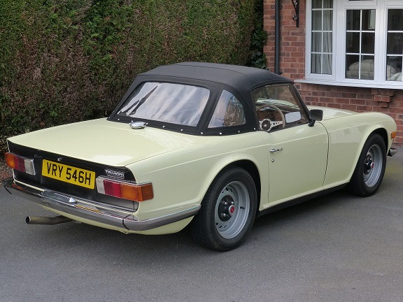
Here is a photo of my TR6 hardtop, with the rods fitted, prior to fitting the headlining.
Martin
.thumb.JPG.3c592666c9d8f14b4cb8222991626097.JPG)
-
I think the TR250 (and early US TR6) heads had a narrower inlet port spacing, so as Graham said, if you still have the original TR250 head fitted you will need to change this to convert to PI
Martin.
-
Looking on the Moss web site:
9inch rear drums were fitted up to TS5442, which is confirmed by my car which is number TS2453 and has 9in drums.
Wheel cylinders and abutments ran through to TS13045, so yes sounds like they should be interchangeable.
Sorry, don’t have any spares.
Martin
-
I thought the TR250 and early carb TR6 heads had narrower spaced inlet ports, so you really want an inlet manifold to match the head?
-
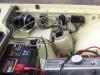
Pic 3 looks like the clutch master cylinder bracket from a TR6 to me.
Martin
-
Hi Martin,
A while back Stuart provided a really good description for the whole process, which is what I will be following when I attempt mine sometime later this year.
To find, do a search on this forum for “Replacing an inner sill without removing the body”.
Martin
-
Hi John,
My commission number is TS2453L.
I bought it off John Saunders in 2013, who at the time had recently imported it from the US, but I didn't have time to start the restoration until Summer 2016.
Martin
-
That sounds a very sensible explanation for the discrepancies in the parts listings.
I still plan on building mine without these seals, being stick on they can always be fitted later.
Isn’t it great we still have some access to those who ran our cars originally?
Martin
-
Just to confuse the issue further my Spare Parts Catalogue, Part No 501653 Amendment 1, dated May 1961, has the identical plate AK illustration as Iain’s, but with detailed differences for the part numbers.
This would imply to me the lower door seal was not fitted until TS 22014, which was the first TR3A on 17 Sep 57.
I am currently restoring an early long door 2. Based I this I am not planning to include lower door seals; that is unless I find water ingress an issue, when I may fit stick on seals, which is possibly what the original owners did.
Martin
-
In the interests of maintaining the forum as a future reference source I thought I should resurrect this old post to confirm the final outcome.
If you remember my car is a long door TR2, on the original wire wheels adaptors which are integral with the hubs. The problem was I could not pull the hub off the half shaft, the splined collar holding it on was stuck and access down the wire wheel adaptor very limited. I borrowed a bigger three legged puller but just could not move it.
In the end I took the half shaft with hub it to TR Enterprises and left it with them. Apparently it put up a significant fight but in the end they managed to separate the hub from the half shaft, and the good news is after a quick clean up all the parts, the half shaft, splined collar and hub, should be good to reuse.
So I can confirm if at first it won’t come off, try a bigger puller/press/or what-ever you can find; it will just pull off eventually!
Martin
-
You might find these links helpful:
http://www.tr-register.co.uk/forums/index.php?/topic/41514-door-water-curtain/
and this one also has a link to a post on the 6 pack forum has some good images:
Martin
-
Hi Andrew,
I also have the same loom from Autosparks.When I asked for the additional relays for main and dipped beams, and electric fan, they asked me where I wanted them. I said around near the existing fuse box and in the end I mounted them in the inner wing, next to the existing fuse box.
From memory the relay holders all clip together, so I have just screwed them to the panel.
Regards,
Martin -
Hi Bob,
The bulbs arrived this morning,
Many thanks,
Martin
-
Thanks for all the replies guys.
Chris,
I'm not referring to the collar the wire wheel locates on, but the internally splined tapered collar (part No 108608) that fits into the end of the hub itself.
My concern is if I simply try and pull the hub off with the tapered collar still in place, the taper will force the collar to grip the splines even harder.
Presumably that is why it is there in the first place.
Also as this part is showing as NCA on the Moss web site, I don’t want to risk breaking it.
Have others succeeded in pulling the hub off with this collar still in place?
Martin
-
Hi all,
As part of a long term restoration I am still taking parts off my long door TR2, and I’m now having difficulties removing the rear hubs. The car is on wire wheels with the original lockheed axle, and has the alternative hubs with integral wire wheel adaptors.
The problem I have is I am unable to remove the splined collar (part 51 in the Moss catalogue on page 78, part 42 in the workshop manual). Because of the wire wheel adaptors I am finding access very difficult.
Both the workshop manual and the Technicalities CD article simple state “Remove the nut, washer and the splined taper collar from the axle shaft”. I have removed the nut and washer but the splined collar won’t budge!
Can I pull the hub off without first removing the splined collar or will this cause more problems?
Also the Technicalities CD article specifically states to use a two-legged puller. Due to the depth of the wire wheel adaptor my two-legged puller is too small, but I have managed to borrow a three-legged puller. As the Technicalities CD article was very specific, is there a problem using a three-legged puller in this application?
Thanks in advance,
Martin
-
Hi Roger, many thanks for your replies.
Thanks Don H for your PM as well,
Martin
.JPG.103c4ecfe517abf5f50c91ffa9963969.JPG)

TR3a fibreglass panels wanted..? And found
in TR2/3/3A/3B Forum
Posted
Hi Hamish, I have two front wings, two rear wings and a TR3A front apron going spare. I have sent you some pic's in a PM.
Martin