


TRier
-
Content Count
172 -
Joined
-
Last visited
Content Type
Profiles
Forums
Calendar
Posts posted by TRier
-
-
On 3/15/2023 at 11:11 AM, TRTOM2498PI said:
Hi Niall,
I hope the attached image helps here.
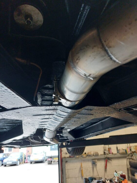
Gotcha, thanks that totally clears that up. I thought it might be that but best to ask. Good thinking. I am not at this stage yet with my restoration but in doing some research I came across these guys in Holland(see the link below) who do a range of round to oval fittings and tubing in stainless, might be a useful alternative to the upside down breast plate. I'd have a slight concern that the breast plate this way is like a scoop underneath on something which is already low, I'm probably worrying about nothing. Neat job though, well done.
-
-
Hi John, sent you a message.
-
Ideally I suppose one wouldn’t be hitting nice spinners with anything, this tool looks very good. Haven’t tried it but I’m going to.
-
8 hours ago, harlequin said:
So long as you go no bigger than 165 tyres they work fine for the road wheels, the one big downside is that the spare will not fit into the storage locker.
My way around it is to have a 48 spoke 4 1/2 J for the spare, a TR version of a space saver
")
George
I was wondering how I’d get around that, thanks, I’ll do exactly that.
-
7 hours ago, Nigel C said:
easy to keep clean and high gloss would help with the contrast of the matt tyre wall.
Try flatting one down and spraying it before you remove tyres etc (if fitted) doing one and not liking it is easier than 4...IMHO of course
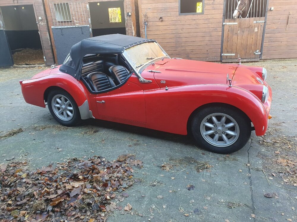
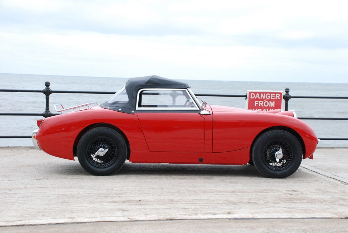
Yes that was my thinking, both re the contrast with the tyre and doing one. I think that’s exactly what I’ll do, might just do two with rattle cans and set them against one side and see what it’s like. My friend (thanks Niall Callery) sent me this photo last night as an example, looks good I think. Generally I like Minilites but not so much on this car.

-
Hi guys, not hijacking the thread here but has anyone any experience of or seen wires painted black on a TR3A? I'm new to TR3A ownership and bought a non running but almost finished restoration some months ago, I have it running and driving now but want to change the wheels to get a more orginal/period look. I have a set of TR6 wire wheels going spare which require refurbishing and whilst I'll definitley go the painted route I was idly thinking about trying a gloss black rather than the grey. I saw a Healey at the NEC with black wires and liked it. Any thoughts or photos?
-
5 hours ago, Waldi said:
I made this comparison when I selected mine:
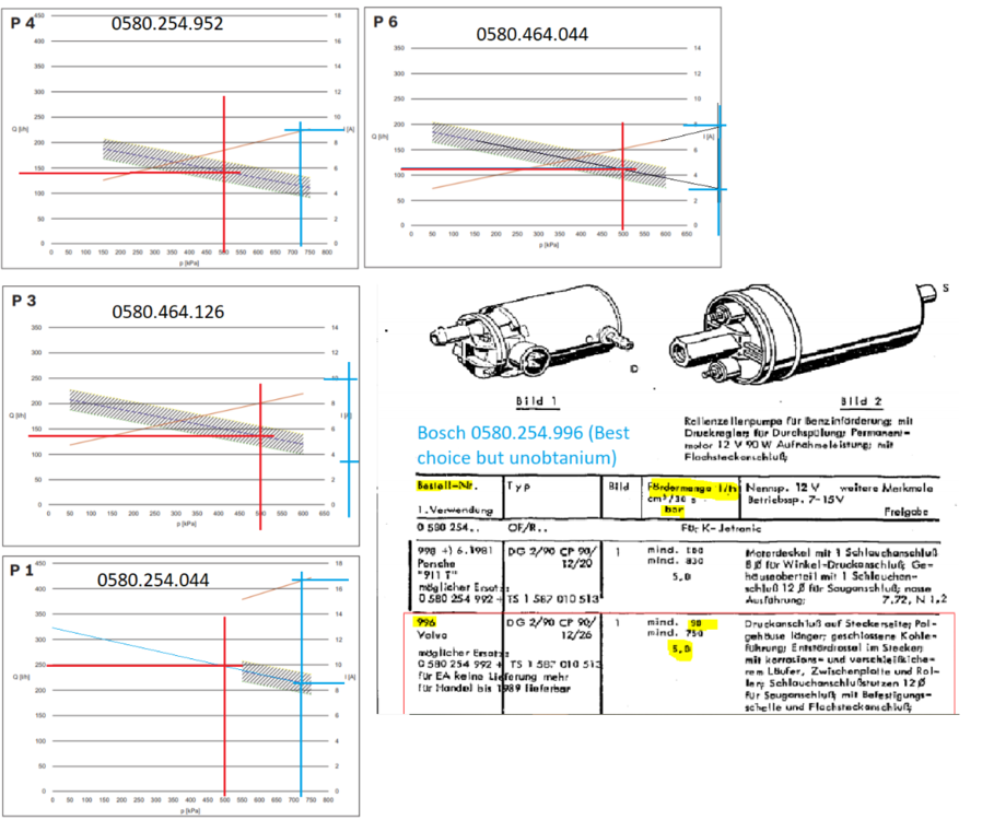
Does that 0580.464.126 work with a max delivery pressure of 5 bar?
-
10 hours ago, Ralph Whitaker said:
To be honest I wouldn`t bother about the front corner of the door cards anyway. My car is post 60000 with the rounded door corners, and when I made the door cards I made them square so that they fill the door aperture when closed and do not leave a gap at the front lower corner. I did use plywood rather than cardboard though, so the overhanging corner has a bit of strength to it. You can see on the photo how far in the screw had to be placed to get a fix compared with the other screws.
Ralph
That’s exactly the situation with mine, i didn’t even notice the situation with the doors closed, much more obvious when I took the door off.
-
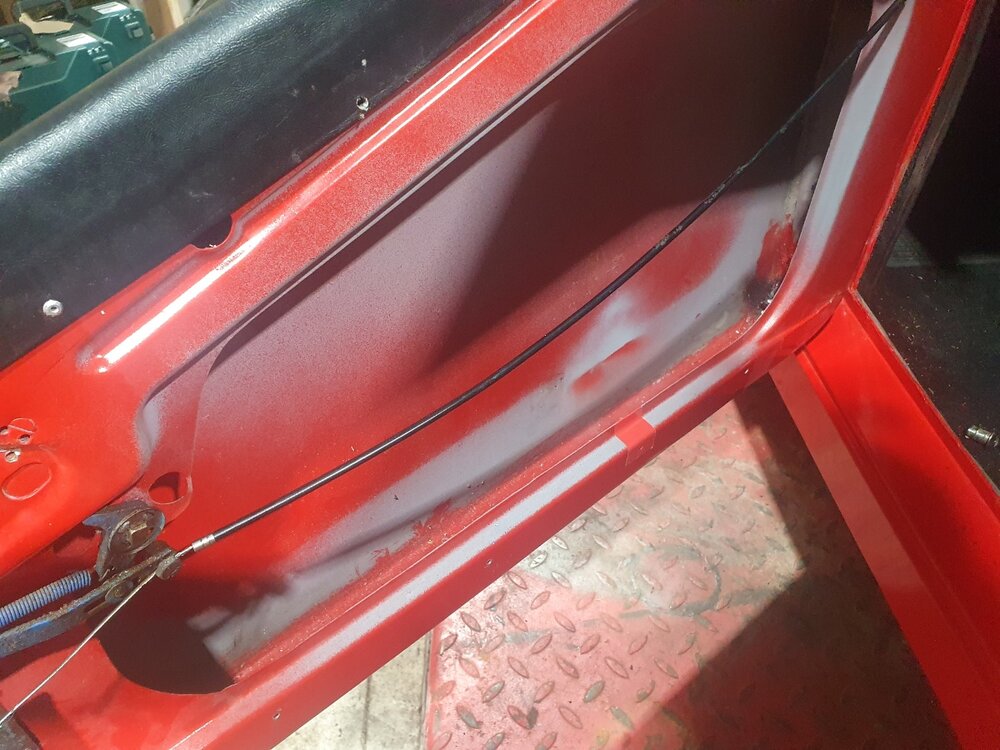
11 hours ago, Lebro said:
The other clue is the front bottom corner, On pre 60000 doors it is a sharp 90° corner, on the later ones it is a curve.
Bob
That’s makes sense of something else, the door cards have a square corner where the door has a curved corner, I bet the door cards are for the earlier door. I’m not going to change it now but I’ll add it to the “long term list” now that I know about it, thanks for the heads up.
Niall
-
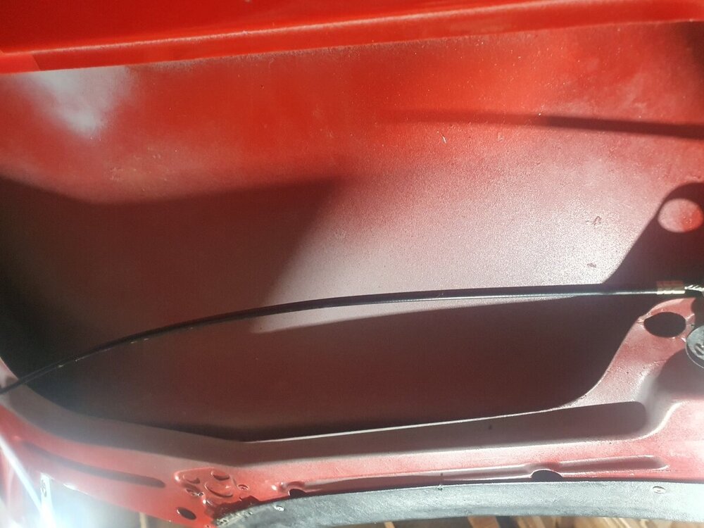
22 hours ago, Ian Vincent said:
From what I can see, that is the door from a TR3a post TS60000. The wooden blocks in those doors are solely where the side screen brackets screw in. I think I can see wood in the holes on the LHS of the picture you have provided. With repeated screwing and unscrewing those holes become worn and you might need to replace the blocks.
Rgds Ian
Yes Ian it is a post TS 60000, I’ll double check for timber pieces in those locations. Thanks for clarifying.
-
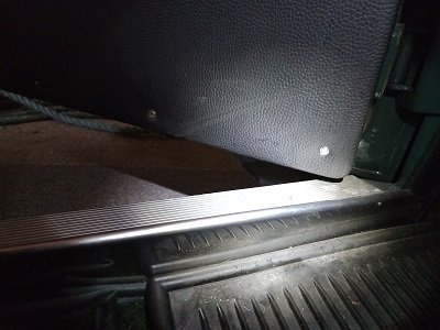
Guys thanks very much for that. I’ll go for the threshold trims in aluminium, that’s the area I was trying to tidy up in fact, it just looks a bit unfinished as is. I’ll probably leave the treads as the clearance between the bottom of the doors and the sills looks very tight and as it’s been painted there is little fettling I can do now without making a big job of it. I’ll check the clearance as suggested though and see.
-
Would anyone have any photographs of a TR3A with treadplates fitted please? I’m looking at PART NUMBER: 900429SS from Moss, interested if anyone has any anything to say about them, also the Moss catalogue seems to indicate 2 required for LH and 2 for RH, I can’t see the logic to that anyone shed any light on that?
Niall
-
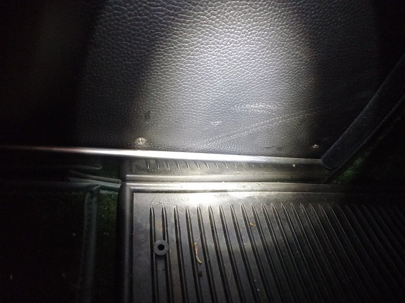
Guys I have just bought a TR3A, it’s been 90% completed by the PO who sadly passed away before totally completing. It needs a little bit of fettling and commissioning so I’ve got to do a little bit of research as I didn’t dismantle the car. I’ve taken one door and door card off to fix a hinge and glue down some of the upholstery and I don’t see any wood and this topic seems to indicate there should be wood inside the door. I’ve taken a few photos of the inside of the door, could any of you send me a photo indicating what’s missing if anything? Everything seems to work ok although the internals of the door handle look ropey and don’t look as I’d imagine were intended they do work but definitely no wood.
(Apologies the photo looking up inside the door from underneath keeps turning upside down in the upload process).
 j
j
-
On 11/15/2022 at 11:01 AM, billy l said:
Hi John, For the indicators I fitted an indicator/ horn push stalk form a Ford Transit, it works well just no self cancel so I fitted a warning buzzer onto the indicators, you can just make it out in the photo. Cheers, Bill.
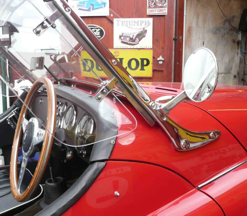
Bill do you mind if I ask where you got those wind deflectors and if you think they are useful? Sorry folks to go off message.
-
Lovely looking car, enjoy.
-
1 hour ago, Bfg said:
I was out in Katie yesterday, albeit only along the A14 a couple of junctions to Curry's in search of an external hard drive that would be compatible with both windows XP and windows-11. I then did potter around with doing grocery shopping before stopping off on the way home for fish n' chips. The 4's temperature, with the TR6 seven blade fan was reading warmer than normal, around about 5 o'clock position on the dial but as it was stable there was nothing of concern.
It was the first time driving the car with just the passenger-side half-surrey-top-lid on. Tbh the breeze was so warm that it was difficult to sensibly assess air circulation within the car's interior, but still it was nice driving the car like that and the driver's window lowered. Airy and cooling but not blustery . . .
Pete

Beautiful paintwork!
-
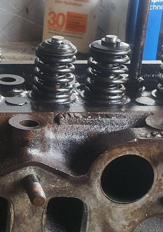
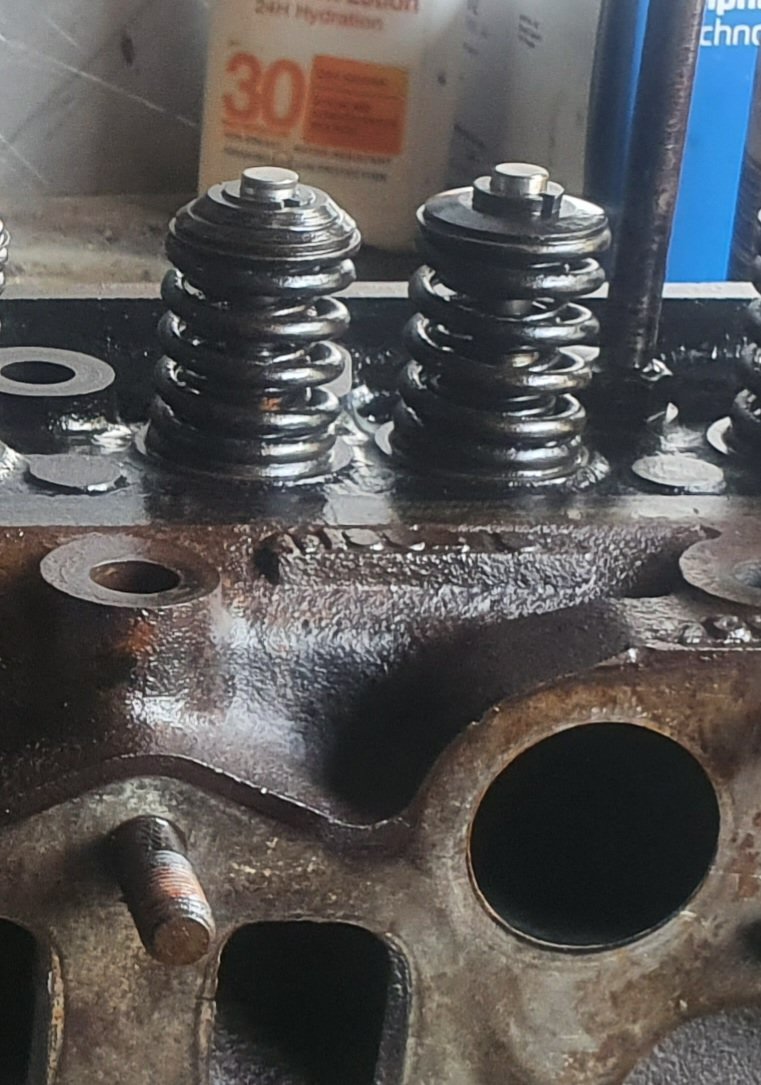
Thanks Harvey, thats a bit of a bummer, personally I'd rather have them as intended. The way the collets sit in the single collar ones just looks insecure to me I must admit, they've been that way a long time so obviously its OK, just looks ropey. I wonder does it not matter then in practice that the exhaust valve can't rotate as originally intended?
-
Moss are showing them as available (the twin collars).
-
Old thread I know but by way of confirmation of how useful the forum is. I'm working on starting an early CP engine (TR5) which has been locked up for a very long time, have it freed up and rotating now but decided to strip the head and give it some attention. I noticed on disassembly that there were differences between the valve spring collet collars, didn't know why but great to see that its been addressed here, I note that somewhere back along the line the head had been reassembled with the collet collars randomly installed. Now changed to 2 piece on the exhaust and 1 piece on the inlet. Great forum.
-
FWIW, I’ve used those expanding reamers Roger linked to and for pretty much the same reason you mentioned. I put new gudgeon pin bushings in a Landcruiser i overhauled the engine in, they were a nice fit until I pressed in the bushings then the pins were just tight. I used the reamer by hand and it took absolutely nothing to just make for a nice snug fit. The beauty with those adjustable reamers is they lend themselves well to getting them square, started with them adjusted slack and in very small bites adjusted them up until they take a tiny bite. They’re tapered so it’s not hard to do that. I took a view that if you go slowly you’re unlikely to do harm and will get everything square. Engines still running 30k later so some indication it is possible at home. Best of luck with it.
-
On 2/27/2022 at 8:49 AM, JohnC said:
Newbie to gearbox stuff, but considering an overhaul. This sounds like a worthwhile change. Is there only one set of close ratios? And do you change the diff ratio to retain the final drive gearing in OD 4th? Or is this really only for racing? I already have a Quaife ATB in the diff BTW.
Hi John, did you fit the quaife LSD yourself or send them the diff?
-
Well done, hope you enjoy it hugely.
-
4 hours ago, CK's TR6 said:
My cam sensor was pretty butt simple. Took a existing distributor (tach drive!) broke the bell off. Turned the remaining stub on a lathe to a cylinder. 3D printed a plastic block to fit over that and that a 3 wire sensor would fit into. Took the original internals and ground off the pivot pins for the weights and trimmed down that plate to be a single tooth. The MS3X manuals talk about when the tooth should be there timing wise. Not supercritical. The software polls the sensor when it thinks it should and the tooth is either there or not.
Yeah that was a good idea, I had similar thought, certainly no harm to have the cam sensor but not sure how much benefit sequential over batch is though. So what has your experience been with the EFI over mechanical in terms of power and efficiency?
Niall


TR6 Turbo
in TR6 Forum
Posted
Got it, thanks. The photo worked!