


TRier
-
Content Count
151 -
Joined
-
Last visited
Content Type
Profiles
Forums
Calendar
Posts posted by TRier
-
-
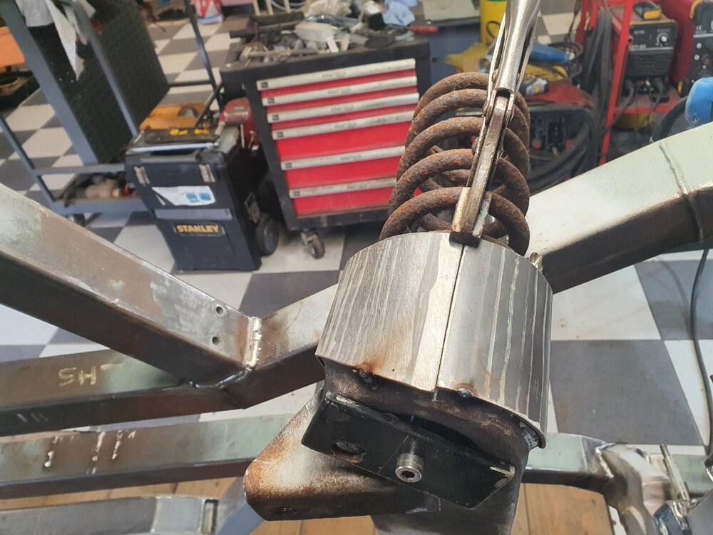
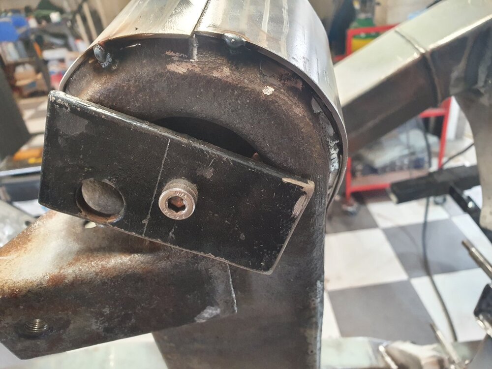
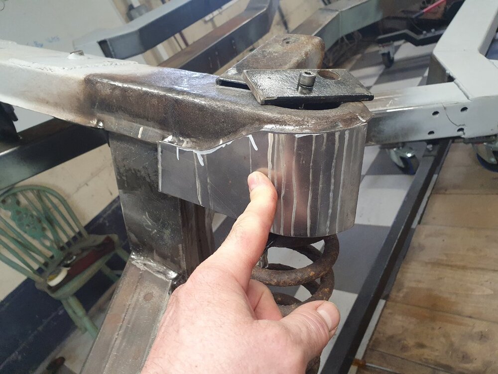
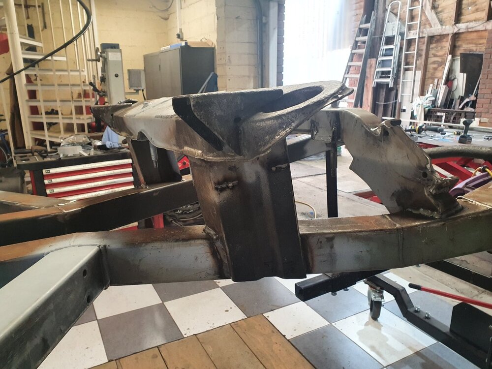
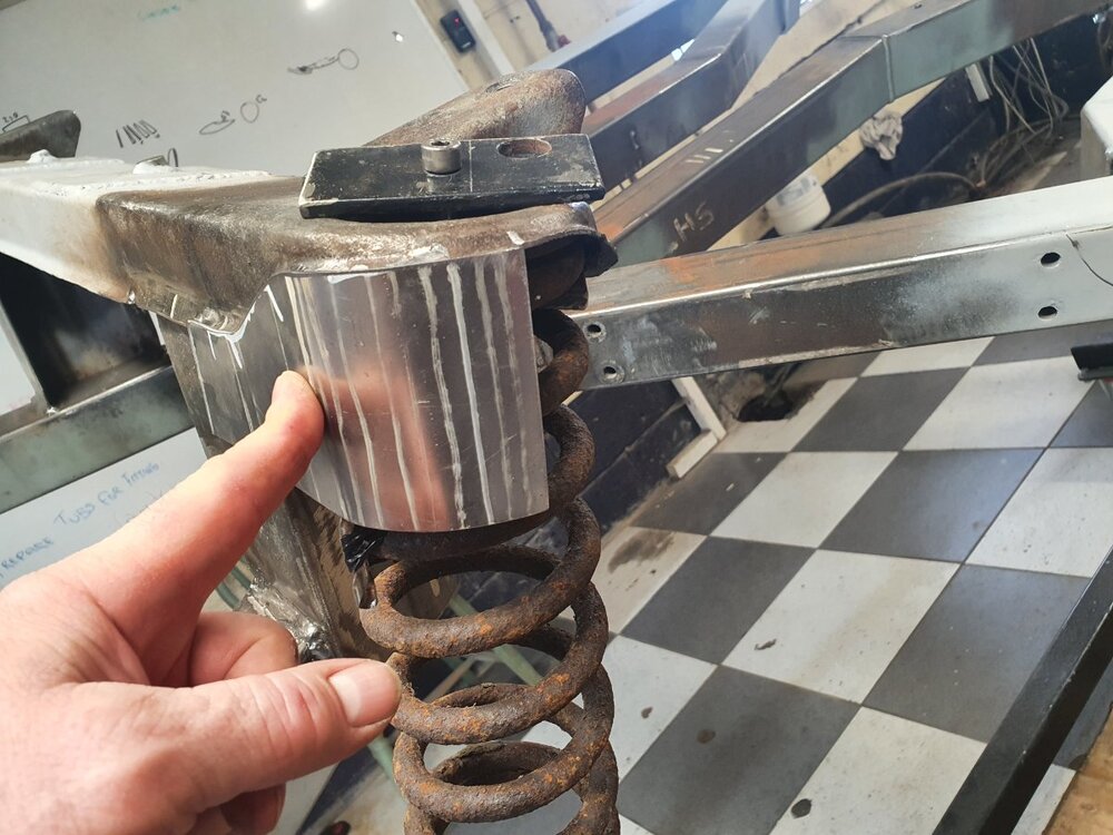
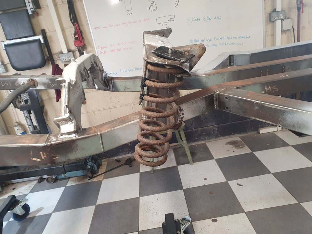
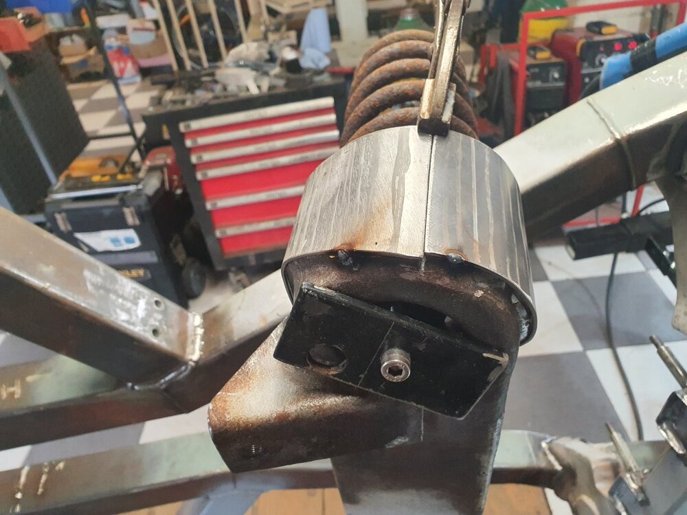
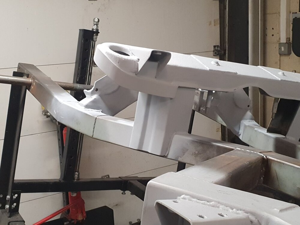
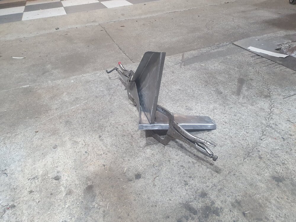
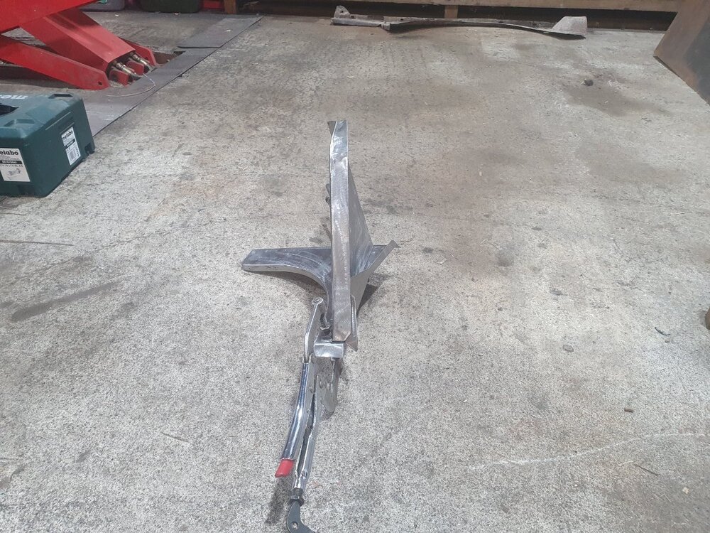
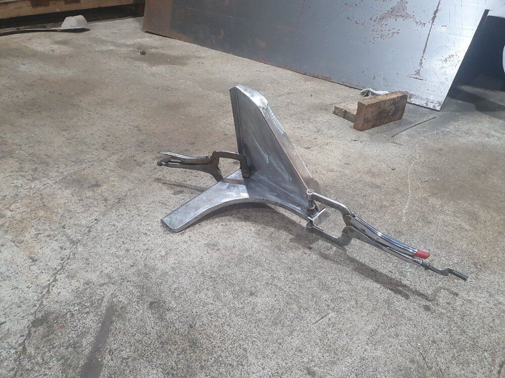
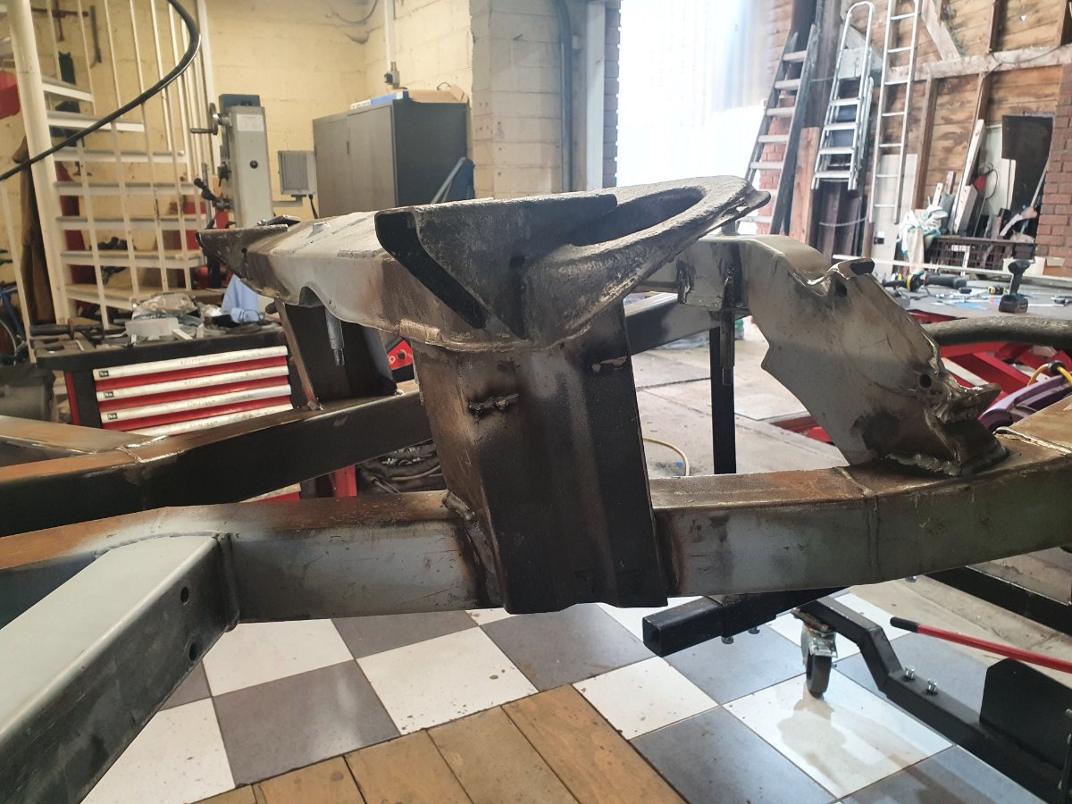
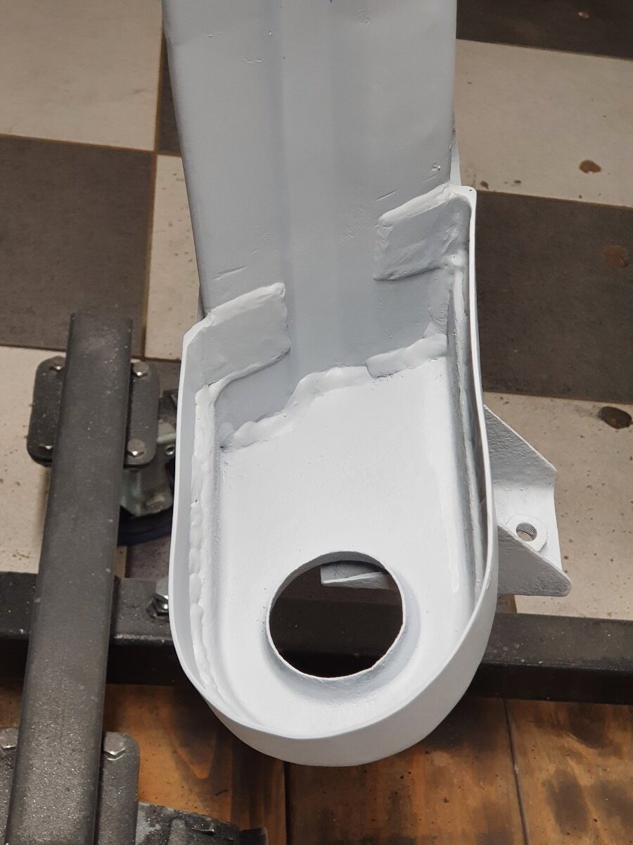
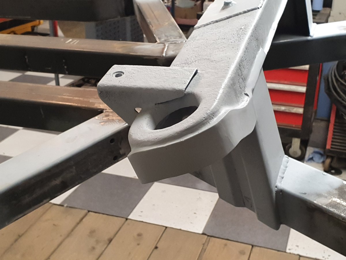
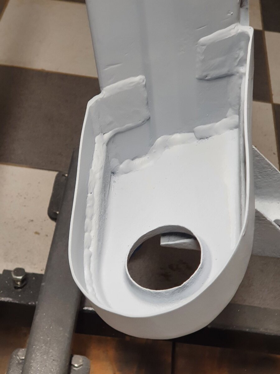
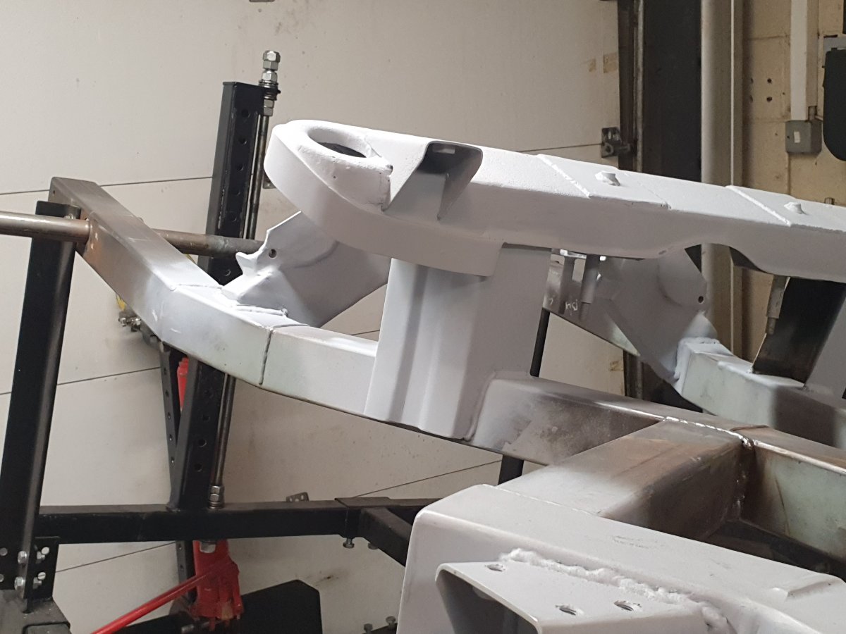
As promised here is some photos of the mock up with spring clamped in place to ensure clearance. Hope its clear.
-
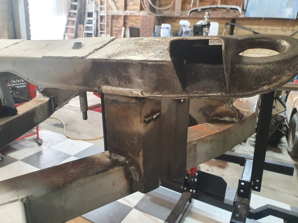
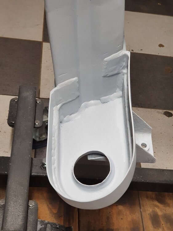
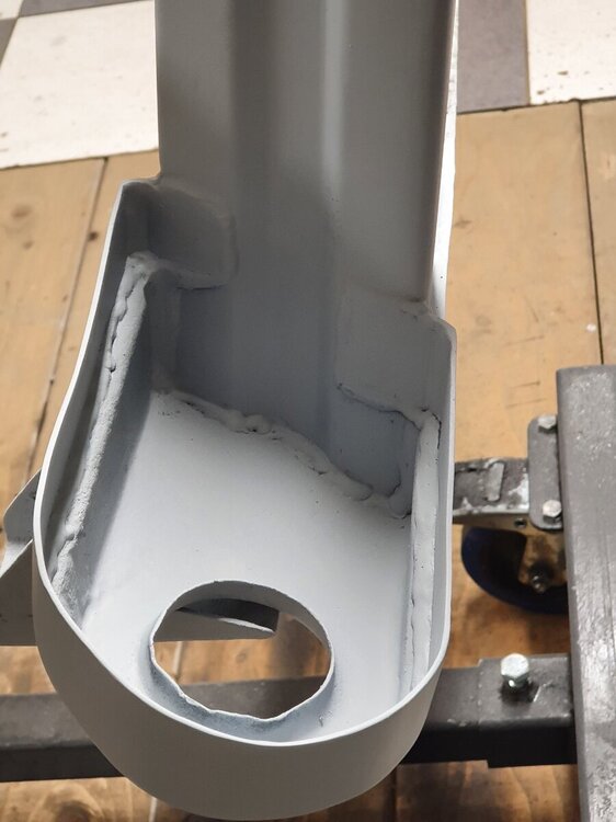
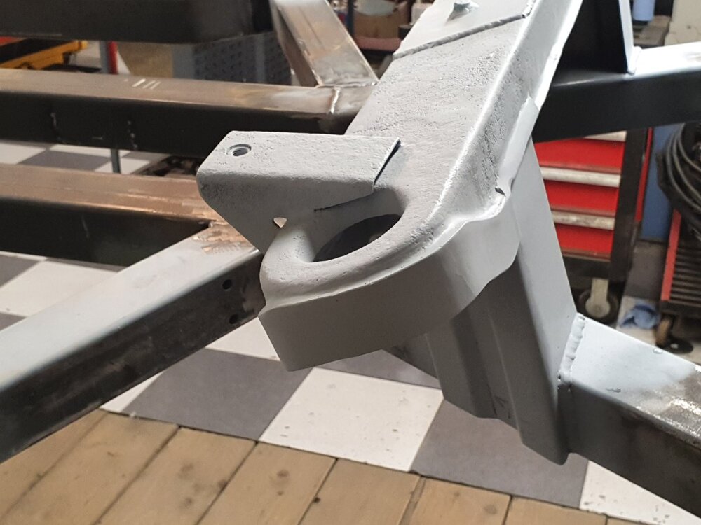
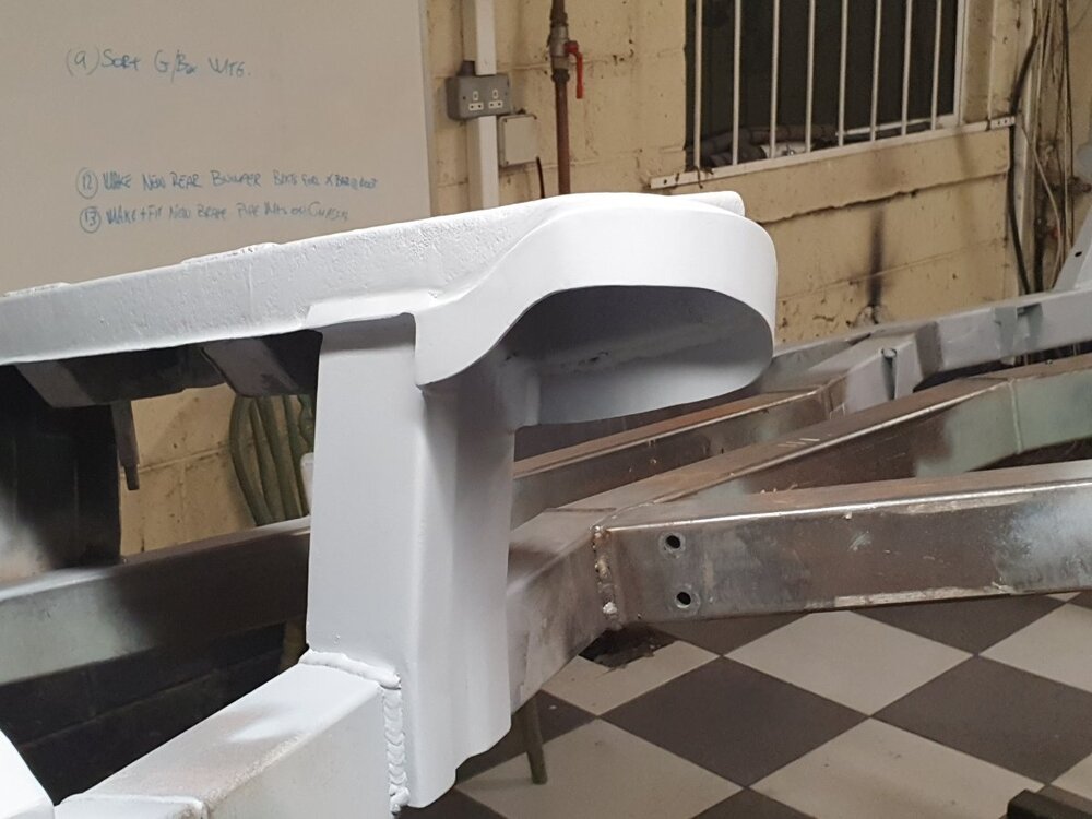
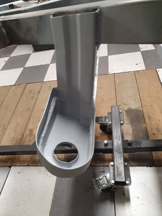
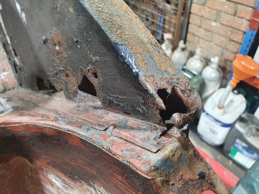
Hi Dave, I reinforced that front diff bridge. I had the same concerns as yourself, although I fabricated a new chassis I chose to retain the top part of that bridge and it was quite heavily pitted and I intend to have the facility to use telescopics so I had concerns about those two ends. I havent completed my restoration yet so I cant say how well the mods work but I'm confident they'll work well, in any case you can take anything useful from the photos or reject the concept as you see fit
 .
.
Personally I think 3mm might be bit excessive, these are in 2mm and its more than enough. I did mock up with the spring in place before I finished forming and fixing these in place, like I said not drop tested in anger yet but definitely enough clearance for the springs in static condition at any rate. I'll post some photos of the mocking up process in a min.

-
It could be the injection system losing prime, as was pointed out leaky injectors but also ineffective NRVs will cause the system to lose prime downstream of the FMU and consequently require more cranking to prime again. With the exception of 5 & 6 they are just rubber discs in the output ports of the FMU, worth a look to check that the haven’t cut “seats” into the rubber discs.
-
6 hours ago, harrytr5 said:
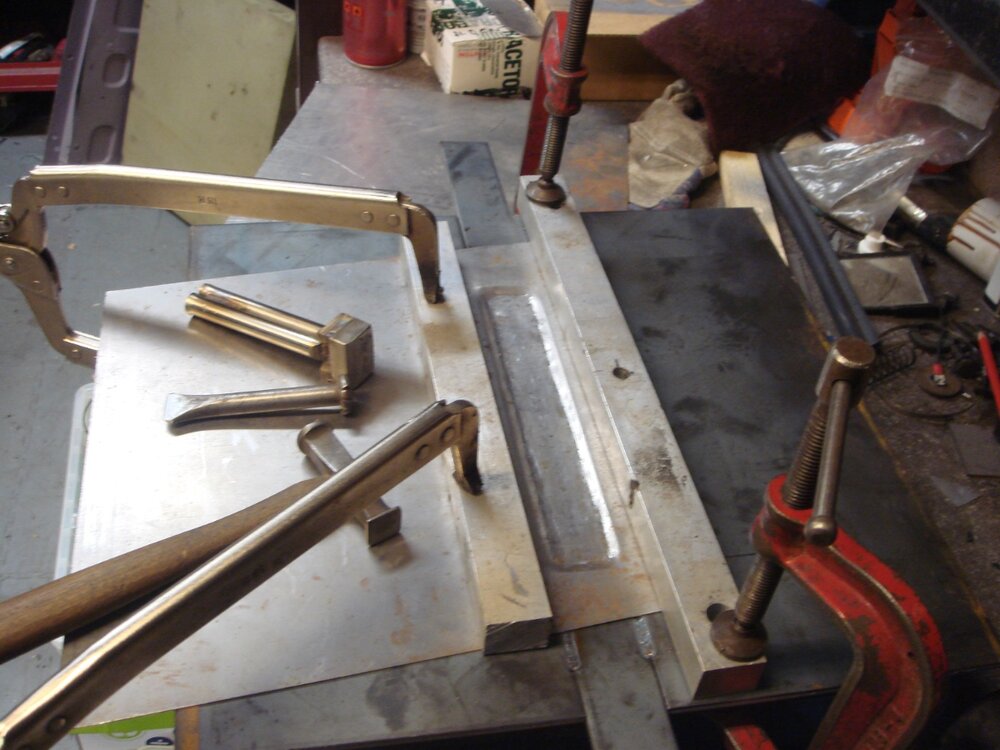
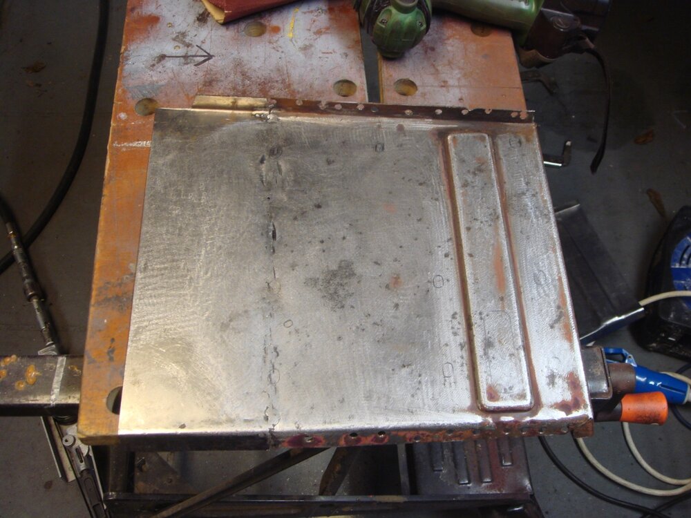
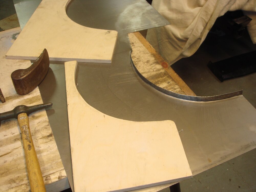
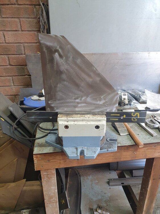
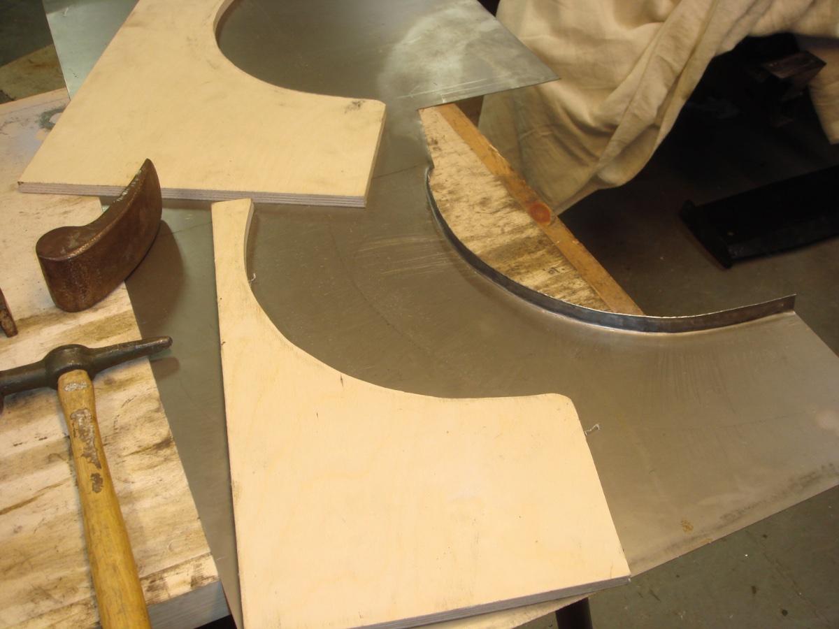
Thought I would show some of my efforts.I formed ply sheets to get the radius right when tin bashing the up stands.
Metal former made for flute work.
Yes I agree very therapeutic and satisfying
Regards Harry
Very nice work Harry, well done. If you’ve put that assembly back on I’d be interested to see how you approached getting it all nicely aligned.
Niall
-
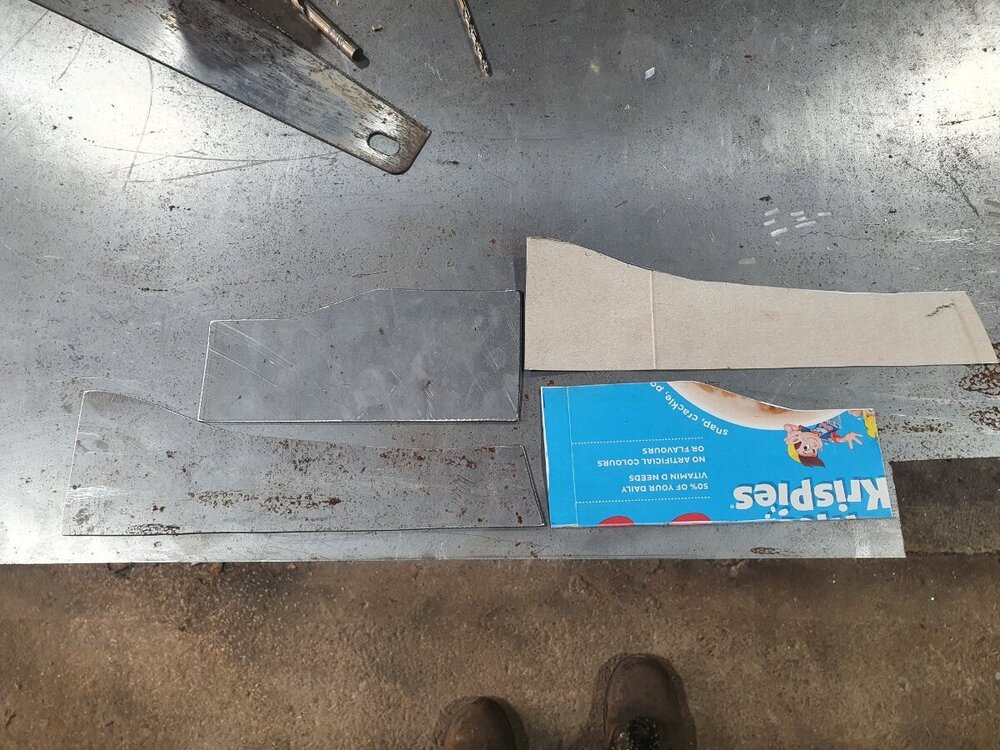
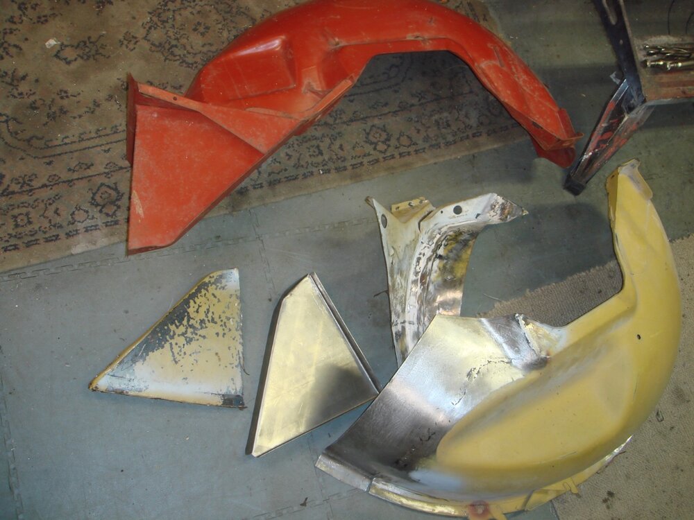
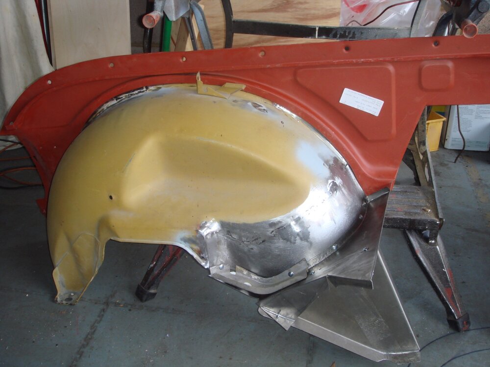
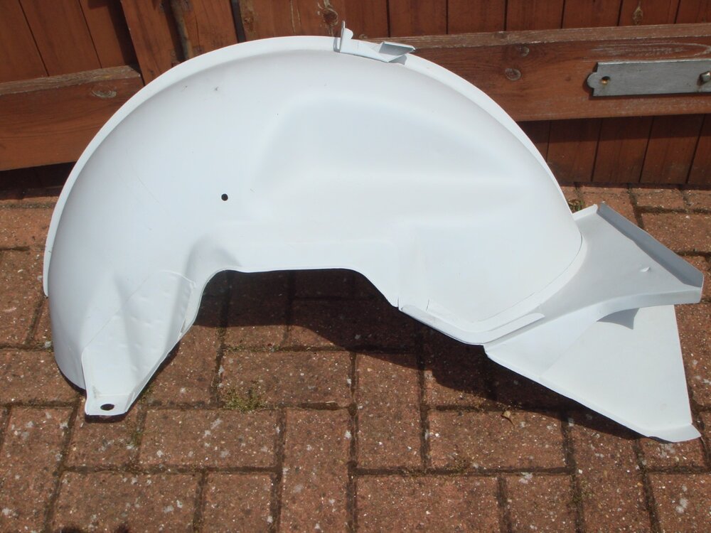
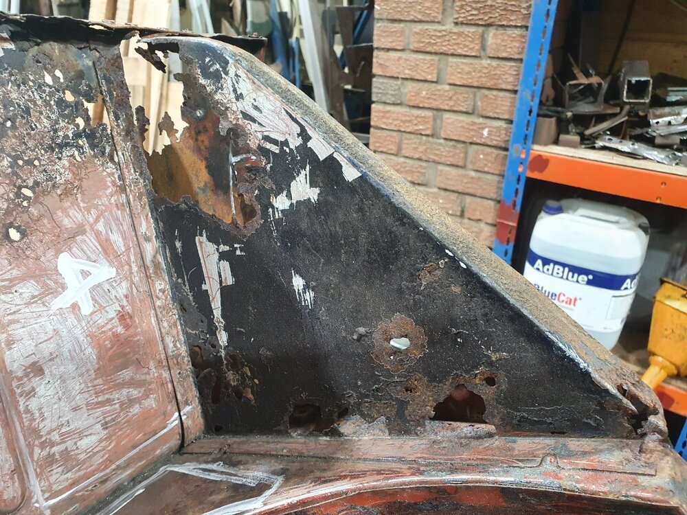
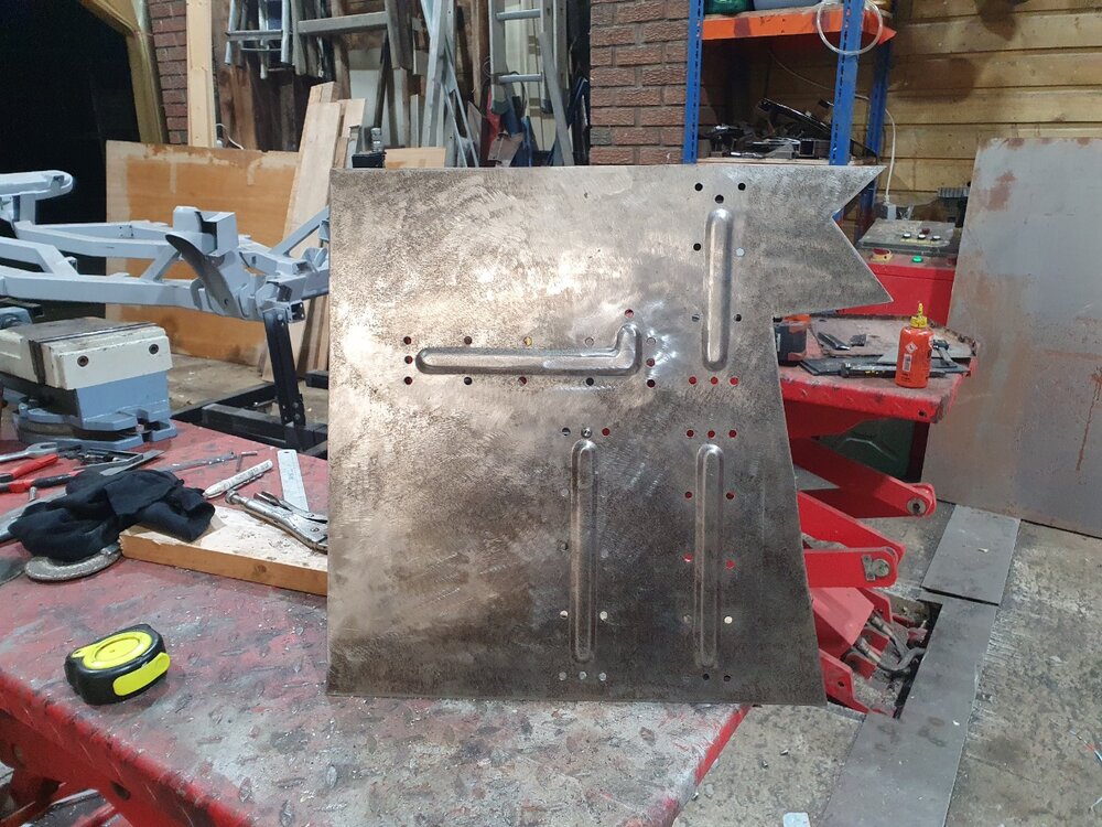
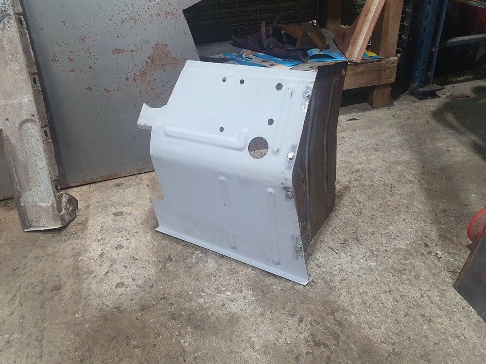
These are from a TR5/6 rather than a 3 but same principles of course. I didnt have to do any body work with my TR3A, mechanical works only, which I guess is why I'm driving it rather than working on it! These are the panels that brace the wheel tubs to the bulkhead, I made three as I've two rotten on my 5 and one on a 6, got better with each one as always. Used the fancy brake press here, might give you a laugh.

-
8 hours ago, John Morrison said:
Lovely work there pal. I'm thinking we met at spares day last year?
truth is I find this bodywork stuff quite theraputic - guess we are similar?
Regards
John.
We did indeed John and you treated me well and gave me great encouragement. It is therapeutic, that said I’ve never made a buck as complex as that one you made for the front panel, I know how the process works but it’s a big undertaking. I’ll be at Stoneleigh this year again, be nice to meet up. Got some great parts there last year.
-
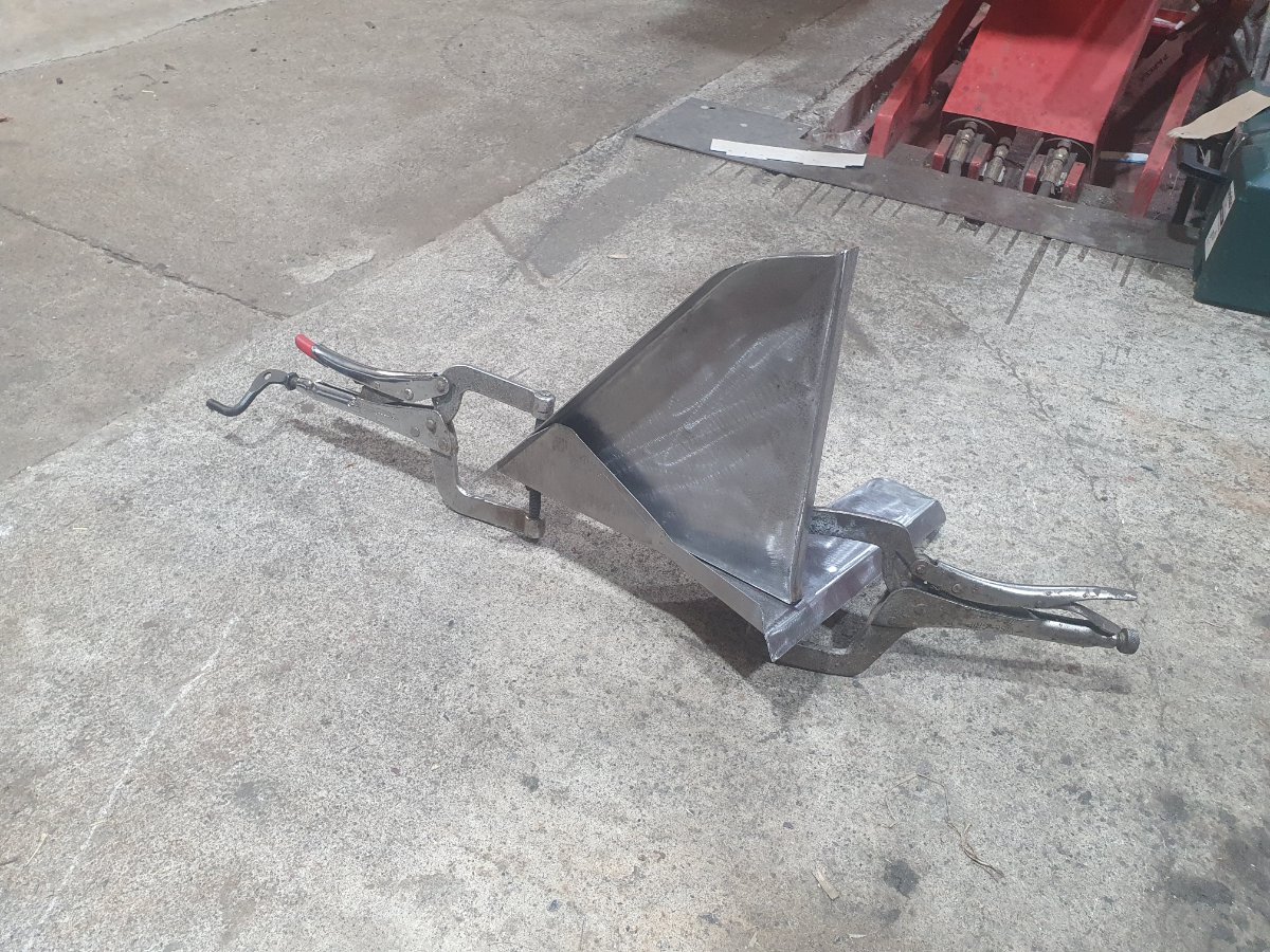
John’s buck takes the biscuit I think but here’s a piece I made for my TR6 using a hand made hammer form die. Further to Iain’s point anyone wants a loan they’re more than welcome and fair warning the reproduction part is only £130, don’t know what that makes me, nuts I suppose, but it’s good practice for the pieces that can’t be bought.
-
That’s lovely work John. Well done.
-
7 hours ago, Lebro said:

 Click on to enlarge
This shows how mixture can vary between cylinders fed from the same carb
Bob
Hi Rob, that's an interesting one. What did you find that down to?
-
Hi Rob, I’ve recently overhauled the H6 SUs on my 3a and tuned it with a colour tune, very impressed with it. I tuned it initially according to the “instructions” on the overhaul kit from SU and admittedly in a hurry. It ran quite well, I had done a lot of work to it so went on a 500 mile shakedown, nice and responsive to drive, 23 mpg, not very impressed with that. Got a colortune kit and re tuned it, couple of videos attached here, one showing number 1 running too rich and the second one showing it pretty much right. After re tuning with colortune I went to Spain for 10 days, 1800 miles, full luggage, 2 up and roof down, I did two tests over th 1800, 35.5 and 35.7. The speedo is right.
So videos showing the colours aside, I found that the front carburettor was very fiddly to get right. It did not adjust as easily as the rear one, tended to max out the mixture screw and then with it maxed out be close to right but not perfect. I was loath to take the carb out and do a realignment but in the finish I had to, it took a couple of goes to get a nice linear smooth dropping of the piston on that carb, I almost gave up on the basis that something was wrong with it but luckily in the finish it came right. Then with the piston dropping nice and smooth the mixture adjustment worked properly, it required a bit of fiddling. The other thing that’s important is to use the two little spanner’s that SU give you or make one, you have to lock the adjustment base with a spanner when adjusting the back nut and it’s a bit awkward, if you don’t hold that outer hex whilst adjusting the backnut then it’s difficult to get repeatable results. I haven’t put an AFR analyser on this thing yet but I will at some point but the mpg and it’s performance in mountainy country would indicate it’s pretty much on the money.
Worth all the effort though. Hope that helps. -
Great post everyone, thank you.
-
On 11/25/2023 at 4:05 PM, david ferry said:
Standard ones are very poor quality.
Buy one of these, or a pair and replace both.
https://www.revingtontr.com/product/650021hqk/name/bonnet-hinge-tr3-3b-chrome-plated-pr-high-quality
Wow they are expensive, eye watering!
-
On 10/25/2023 at 10:04 PM, Quicksilver said:
trip to ireland in 2024 is on the list ....with 21 TR's from Holland...so maybe we can take it to the our tour plans...
Marcel.
Keep in touch Marcel, if you need any help with itinerary or support I’d be happy to help. Kerry is lovely driving country and well served in terms of accommodation and sightseeing. West Cork similarly, beautiful countryside, sights and things to do and it would be on your way into Kerry. Make sure you start to organise accommodation early, with war refugees and so on at the moment accommodation can be tight. Donegal and the north of country is lovely driving country too but the weather can be not quite as nice as Kerry and Cork so personally I’d go south, perhaps over to the West where you have lovely coastal driving roads and beautiful walks, sightseeing and accommodation, Clare, Connemara.
Big number of cars like that it may be that someone will want spares or help.
niallpower.power@gmail.com
-
On 10/26/2023 at 11:27 AM, Nigel A said:
I’m doing the West Coast of Ireland next year with one of my friends. We are going with Scenic Car tours and I’m taking my TR and my friend is taking his Stag
Nigel
Take my contact details there Nigel and keep in touch and if you need anything locally beforehand or whilst you are here I may be able to help or offer some pointers. niallpower.power@gmail.com
-
Hi Cas, I get the same thing, really severe, it can take several hours to recover. A lot of factors can provoke it, the under the car thing can be associated with not being able to get the object of your attention in the correct focus range for your eyes or glasses because of the space restriction. It also seems it can be blood pressure or maybe inner ear associated, for example working upside down under the dash is guaranteed to make me sick, you'll probably need to be careful with that. Remove the seats and try to make it as easy and quick as you can with the upside down bit.
As others have mentioned, a lift as you get older becomes almost a must have, being sick takes all the pleasure out of the work. You'll develop tools and techniques to avoid where possible the situations that make you sick. It developed with me as I got older, I've tried balance specialists and physiotherapists specialising in vertigo (yep there are such things), by all means try, for me I couldn't get any of it to work so just tried to get a bit smart about how I tackle things. Wish I had a better answer for you, it is what it is I'm afraid.
-
I have observed a similar issue, similar but slightly different and I'm not convinced that its electrical noise. I have the opposite problem, I have a Pierburg vane type electrical pump fitted and it audibly surges and subsides with the flashing of the indicators, one wouldnt notice this with a diaphragm type pump as its effectively always surging and subsiding anyway. There is no pressure loss and no loss of function on the indicators, they are just normal incandescent indicators by the way, so I havent bother yet to do much in the line of investigation but I was putting it down to voltage surges or fluctuations caused when the pump is running and the car is only on tickover and charging is marginal. Thinking about it here I doubt its anything to do with charging and possibly more to do with the fact that both the indicators and the pump are grounded close together there at the back of the car, I think I will try feeding the pump through a relay which I need to do anyway and/or bringing it a cabled ground from the fuseboard/battery negative. Trying these would identify if the problem is electrical noise or power surges. Your indicators would be supplied from a flasher unit (relay) at the front of the car anyway and that should provide electrical isolation from the pump supply and noise there locally at the back, but not any ground associated issues if they exist. Well worth a look, supply the pump and or the indicators with a temporary ground cable from the battery and see if that eliminates your problem, if it does then you know where the problem lies.
-
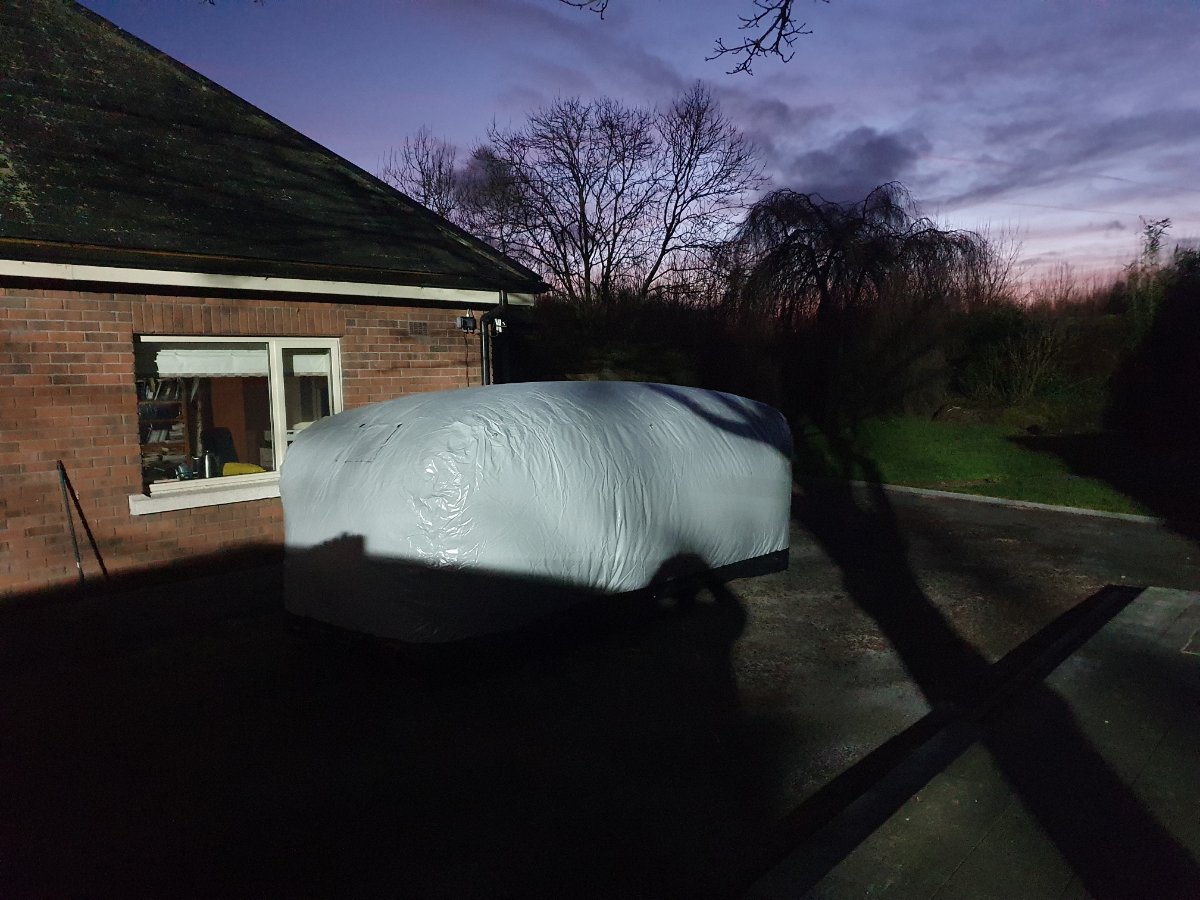
I have been using an inflatable shelter from a a company called IntheGarage for the last year, store my TR3 in it, I'm in Ireland and so it gets plenty of wind and rain. I have been very very pleased with the product, so much so that I've ordered another two just now. I did quite a bit of research when I first bought it and would make the following observations,
1) Do some very careful research around Carcoon and the service in the sales and after sales process.
2)The Inthegarage item and probably all of the inflatable types do have that very slight pain in the ass factor that you have to cover and uncover the car before you can use it. Its a very slight issue, it deflates in a minute or so and inflates in approx 2 mins. If you are very particular about your car and its paintwork there is a bit of a concern about pulling the inflatable cover over and back across the car as it is quite a hard plastic as it needs to be to be robust. My advice if you are very worried about any possible marks to your paintwork is to put a light cover over the car and then pull the inflatable material over the covered car, same in reverse, one person can then cover and uncover the car without any worries about scuffing. I dont actually do this tbh, I'm not that precious about the car and it is a driver rather than a show car, that said I just cover and uncover it with a bit of finesse and I haven't had any marks or scuffs.
3) In high winds and locations with high winds I would put some heavy rubber matting on top of the base of the inflatable and then drive the car onto it and inflate. I have done this and find it makes it really really stable and I dont worry about storms, I also think it protects the base from possible punctures from small stones or debris pressed into it by the car tyres. Plywood could work as well perhaps if you are careful with the edges and keep them close to the car wheels, I think spreading the load over an area instead of just the areas of the wheel to ground contact helps with longevity on the bubble. Certainly it got a lot more stable in storms after I laid down the rubber matts over the base and then parked the car on them, that said I dont use tie downs at all, I could but found no need with the mats. I have storage in sheds but I'm going to use these units inside the sheds as I have found they do a great job, not just in terms of moisture but dust too.
So there you go, they work, preserve the car perfectly and no reason you couldnt put a small oil filled radiator in them if you really wanted to. Dont be without a car if you have room for one of these units.

-
1 hour ago, stuart said:
I have fitted one of those conversions before, The Mini rack is actually a left hand drive one upside down as the TR fitment is in front of the axle line and the Mini one is behind. I wasnt hugely keen as I thought the mounting bracket was a little flimsy. It also required the O/side engine mounting to have a little bit shaved off one side for column clearance.
Does yours look like picture below.
Stuart.
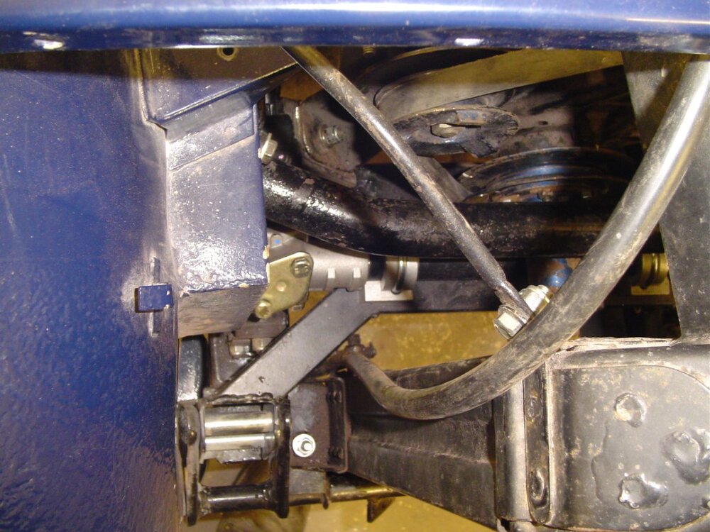
Looks the same I would say.
-
1 hour ago, stuart said:
I have fitted one of those conversions before, The Mini rack is actually a left hand drive one upside down as the TR fitment is in front of the axle line and the Mini one is behind. I wasnt hugely keen as I thought the mounting bracket was a little flimsy. It also required the O/side engine mounting to have a little bit shaved off one side for column clearance.
Does yours look like picture below.
Stuart.
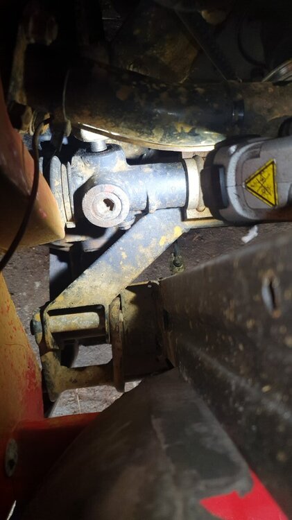
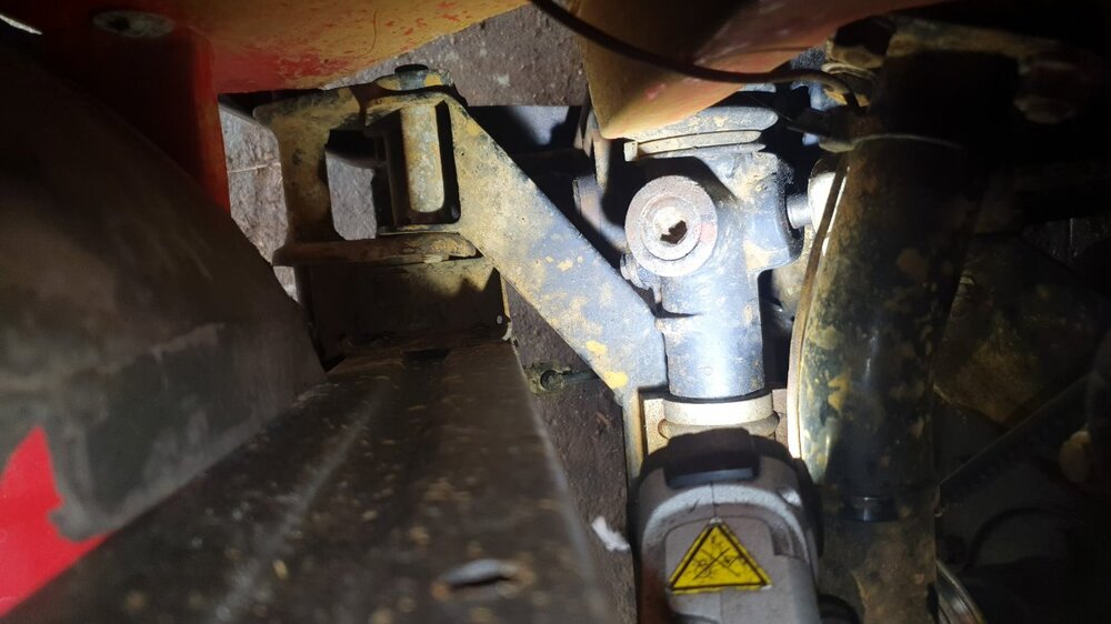
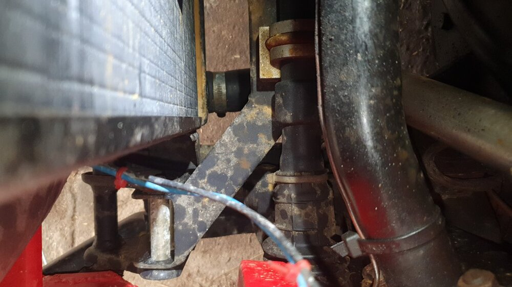
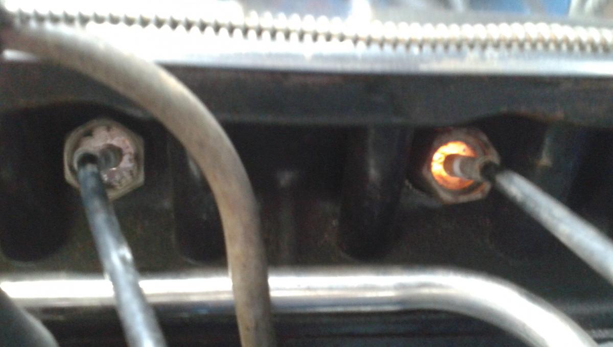
Yes thats it, excuse the dirt, I've been chemical flushing and had some boilover not cleaned up yet, heres the as installed photos. Rack doesnt seem to be exaclty the same but brackets the same fabrication I would say.
-
Hi all, I contacted TR Shop who supplied the conversion kit originally (I got a file of receipts with the car) and they have come back to me with a manual they supplied with it, turns out its a Mini rack. Hats off to them, they came back to me quickly after I reached out and it is something they sold 11 years ago, I've never dealt with them so there's currently nothing in it for them. Anyway, now I know its a Mini rack and have a manual for fitting it so at the weekend I'll get stuck into investigating whats wrong and come back with news or further questions, right off the bat I notice that the conversion booklet says that the original LH and RH steering arms should be swapped. I dont know why yet but possible issue there and I also note that the mounting bracket for the rack is "sided" and the instruction sketch makes a point of identifying which side is which by referring to a "large gap side and small gap side" so room for an error there and its in the nature of what we're seeing here. I'm reassured that its a Mini rack and not some kind of special so it seems more likely now some kind of fitment error than a rack fault, we'll know now soon enough :-).
Probably this is all going to grow legs now in that if I end up taking the front off this car I may investigate and solve the horrible bump steer characteristics at the same time which are probably linked to the height at which that above referenced bracket places the rack. So as a side question, anyone got any commentary on the Mini rack conversions and bump steer?
-
3 hours ago, TR NIALL said:
Niall I may have a MK2 Escort Rack if you need,you know where to find me if needed.
Thanks Niall, generous as always.
-
Thanks guys, I haven't really put any thought into it yet (there were too many other issues) but from the cursory look I did have I'm fairly sure that the height of the rack is far too high for optimal geometry. Probably a bigger issue to resolve and I want to keep the car on the road so I thought I'll sort the basic and most pressing problem first hence the lock query. Good to know you guys are out there for the bump steer too, right now I couldn't enjoy the full performance of the car on any kind of bumpy road that's for sure, very twitchy might be an understatement.
-
47 minutes ago, stuart said:
I think your all going round in circles here so to speak. You need to centre the rack by going all the way from one lock to the other then halving the number of turns. You will then find your steering wheel is out. Take it off and find the correct point where it sits straight. Then remove the outer rod ends completely and take the gaiters off so you can have a look at the amount of thread showing on each inner rod end and check they are the same as some of the racks supplied years ago had too long inner rods which required threading further inboard and then the excess cutting off to allow proper tracking so it maybe this hasnt been done correctly. Also different outer rod ends are around that dont have the same amount of internal threading. Then you will know whats not correct.
Stuart.
Ok now we're getting to the nub of it. There were racks out there back in the day that had an internal issue that needed modification. That's what I feared here and if I were a betting man I'll bet is the case. Like I said I'll do the tests and measurements now and report back to everyone.
Incidentally it does have awful bump steer too but that's another story for another day!
Thanks all for helping.
-
7 hours ago, RobH said:
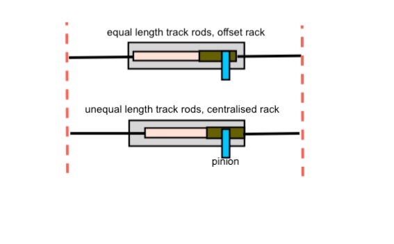
Sorry Niall but you are just plain wrong. Shortening one track trod and lengthening the other by the same amount does not change the tracking, but what it does do is move the geared rack across within the rack housing. That is the only way to correct the assymetric lock If you cannot move the housing itself.
Hi
Hi Rob and thanks for the great sketch, I hope I’m wrong but will just have to make a few specific measurements and come back to you guys, I’ve been wrong plenty of times! Of course if I change both track rods it won’t change the tracking and it would as you have shown effectively re centre the pinion on the rack gear, however in this instance, the track rods are more or less even and the tracking looks more or less correct, so there would be one would imagine perhaps 1/4” adjustment both sides before one would start to say hold on something not right here. 1/2” which would leave each side a full inch different to to the other, one rod effectively at the end of its travel and the other close to or out of the rack would definitely be ridiculous, I haven’t measured the linear distance but the two locks are one full half turn of the steering wheel different! So I just can’t see that much being made up with a tracking adjustment and if it could it would leave both sides at completely different extremes of their adjustments, something is really wrong here, I think.
I appreciate the help so I’ll make some measurements and take a few photos with the adjustments and come back to you. As a parting thought is there any chance that TR3s have left and right hand track rods of different lengths and they were supplied incorrectly back in the day with the kit when the conversion was done?
Niall


Chassis strengthening TR5
in TR5/250 Forum
Posted · Edited by TRier
Hi Pete, as I said I haven't tried the thing in anger yet but I would think with a spring compressor the springs will come out easily enough, but thats a speculation, I dont know yet. Personally I dont like the triangular gusset solution, I think it looks a bit ugly. In terms of allowed, well its not disallowed where I am certainly from a regulatory perspective. There's an interesting chat in there on that subject but this probably isnt the post for it.
Niall