


CK's TR6
-
Content Count
164 -
Joined
-
Last visited
Content Type
Profiles
Forums
Calendar
Posts posted by CK's TR6
-
-
I converted an extra distributor body to a “cam” sensor for the MS3x. This allows sequential injection versus batch. And it simplifies the whole tachometer thing (ie remains as manufactured).
-
-
-
Blair, you did good. The key about running for 15-20 minutes right off is to get critical deposits from the oil deposited on the cam and “flat” tappets. This is mostly to get a good layer of ZDDP deposited at the wear surface between the tappet and the cam lobe. That protects those wear surfaces at the contact point which can see 200,000 psi load. That is why there are break in oils and/high ZDDP oils. And also why using detergent oils is not the best idea as it strips that coating away.
? bone conduite voiture?
Bonnie nuit
-
If my car has any forward motion, it gets direct cold air. My custom radiator shroud it not as wide as the stock. 5” approx less on each side of the grill. on the right side the air cleaner is less than 1.5” from the grill and that side of the shroud is relieved to get it to fit in there. There is a partial shroud around the air cleaner open at the back to direct any extra airflow over that side of the engine. pretty much has been that way since the EFI install. as for cooling, my shroud fits tight against the lower valence, around the horns and up against the radiator. my electric fan hardly ever runs, in phoenix, temps are 100-118f in the summer.
-
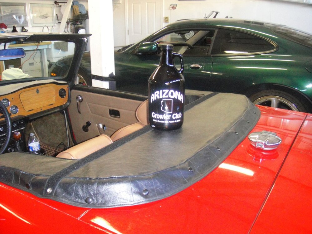
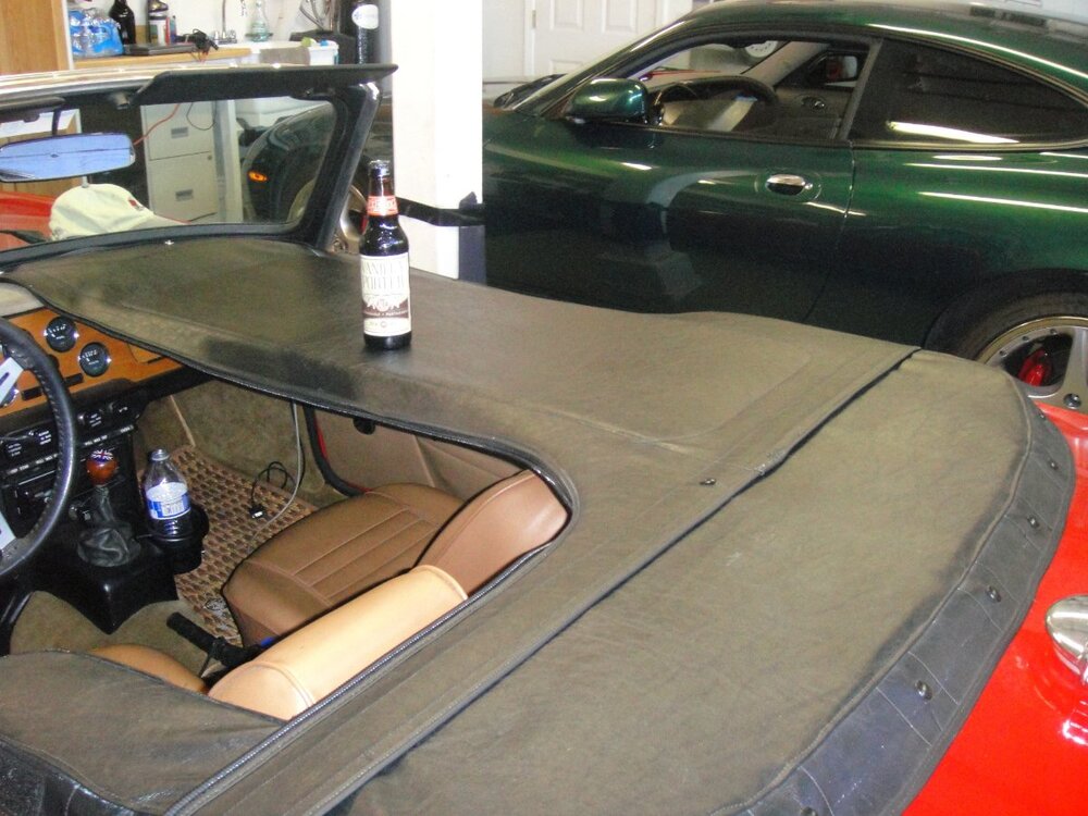
Sometimes, you just can't find what you are looking for. Inspired by the hard cover on a TR3 at Malvern, I wanted something stiff, smooth, sleek if you will but would still go in the boot. So, I made it. The two pieces over the seats have an aluminum sheet slipped inside, the passenger side now has a bar that clips into the seat belt clip to further restrict movement. The back piece has plywood across that has ends that drop down and lock on the hood frame. I learned how to sew with a walking foot machine on this project. It shows but it is super functional.
-
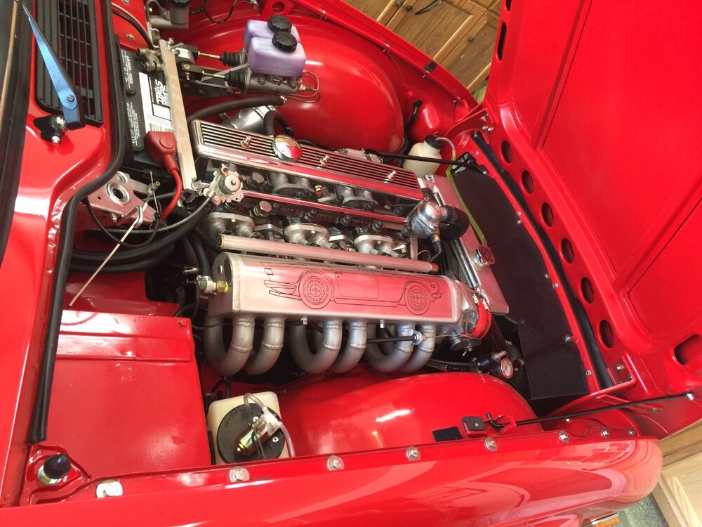
When I built my motor. Nitrided balanced crank, Racetorations main bearing supports, con rods polished peened, Racetorations front/rear sealing blocks, ARP fasteners, Wiseco forged AL pistons at 2.974" with 0.240" crowns for strength, 9.9 to 1, port matched polished ported, 1.55 roller rockers, currently running this cam:
TSI275-6 .425" 275° 3000-6500Flat power curve from TSI, used to have a WBC518NRv2 cam (asymmetric cam) .
My numbers were similar.
-
If you have a spin on oil filter, fill the new one before installing it.
-
I have an alloy cover that the filler cap had a vent hole in it. No matter what I did, there was always oil on the underside of the bonnet. Yes, a air oil separator with a PCV helped but still had some. I fabricated a sheet metal plate that fitted inside the cover and dropped over the two cover studs on either side of the cap. I put half nuts on those for the plate to sit on and put a bend in the plate so that it was sprung up against the inside top of the cover. Problem solved. To add oil, I have to put a flat screwdriver in between the cover and this plate to give a gap.
-
Like any DDD/F uplifting device, my 76 has both (and has had both since it left the factory). The upper one goes to the bumper (or main support for Dolly), the lower to the bracket (underwire if you will). Then, because overly heavy front end loads need ............more support, there are 2 bars that go straight forward to the lower edge of the license plate holder. look at plate 55, and all will be revealed.
If you run straight into a buxom lass, the impact will be most absorbed (ing).
-
If the car still had its Dolly Partons, it would be evident why. Just ask any DDD.
-
Does an Elan handle better than a TC Europa? I drove a Twink for 9 years, across the USA and back, east to west and south to north, and was my daily driver. Stock except for the exhaust header. My 6 has poly bushes, lowering springs, front and rear roll bars, 16' wheels, autocross tires, Konis in front, World rebuilt levers in back, Toyo fourpots in front, Wilwood discs in back, dual master cylinders from Goodparts, HD front axles and GP bearing spacers up front. It corners better than the twink, brakes better, has a ton more room, and isn't as stiff riding as the twink. BUT, it isn't as light on it's feet as the twink. The twink was telepathic, the 6 is not. The 6 is much much more practical and is why I sold the twink and kept the 6 when I needed the money.
-
Asymmetric steering wheel.
-
-
When I went from MS2 to MS3 the tune wouldn’t load. Had to enter everything in manually. I may have a MS2 map around in an old desktop. I will look around. I use an EDIS setup which may change things some. As for VE, 0.030” over, TSI275 cam, 1.55 rollers, port n polish, Triumph Tune header, bespoke intake. 3 bar fuel.
-
There are sacrificial anodes for cooling systems to prevent galvanic action.
-
-
-
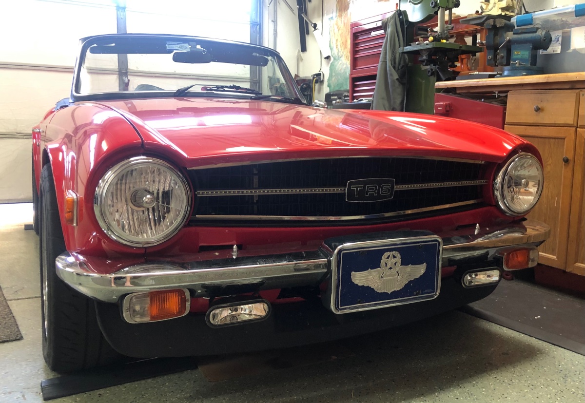
Five years ago before sequential upgrade.
-
If you go to port injection, which means a 3bar fuel supply, here is an idea re fuel routing. Have the high pressure fuel pump, fuel filter and fuel pressure regulator in the back. Have the regulator overflow dump directly back to the tank. Run the MAP reference line all the way to the back to the regulator. The single fuel line to the injector rail works just fine. The air purge time in the controller set up needs to be widened a little but that is it.
-
As a treasonous colonialist, I am a bit confused. To recap, this is a works rally cup experimental 5 speed gearbox with stag internals and an overdrive that works on all forward gears (5)? And it seems that even though it was for a saloon? it had been fitted to a TR6? Holy cow. If Moss had put an overdrive unit on that bespoke Vitesse (Mazda) box, that would be a modern equivalent of this unicorn.
-
I am not so sure about the single throttle body limitation. My engine is 0.030” over, 9.9 CR, TSI 275-6 cam, 1.55GP roller rockers, Moss header, SS valves, bearing cap braces, MS3X EFI, crank ignition and …….a single throttle body on the common plenum of a bespoke intake. I really don’t think it has held the performance back. The TB is from a 4.3l V6.
-
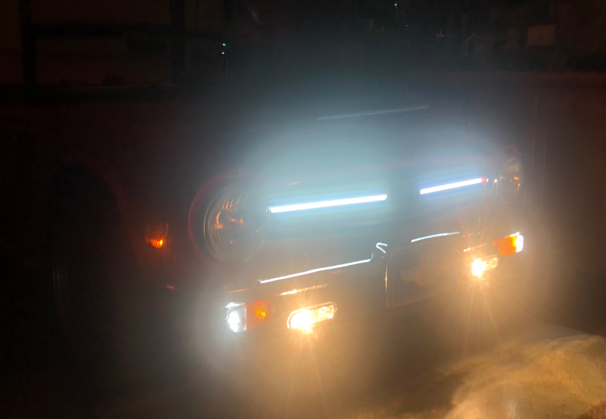
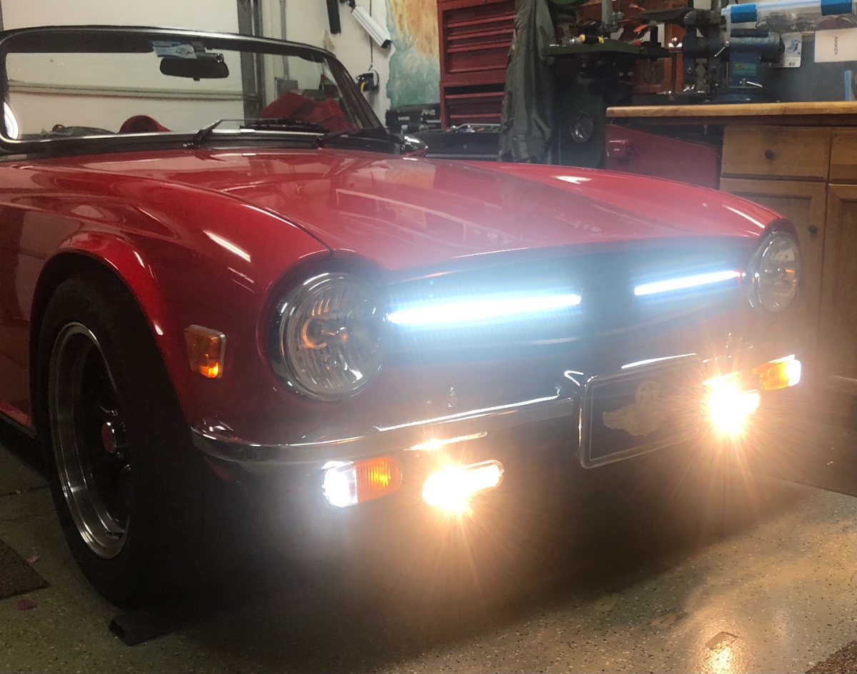
Hella FF75’s. And a little more. I have the running lights on like this even during the day. Headlamps are halogens.


-
In my case it broke like that. Then the gas shock extended to full length. Then when I went to start braking from 65+mph, the whole thing swung forward and the sharp edge of the break cut into the inside edge of my right rear wheel (alloy). Which proceeded to rotate all of this up and jam the cup between the wheel and the frame where it comes out to support the bump stop (down motion) for the lever shock. Just like sticking a heavy stick in the spokes of your bicycle while going fast downhill. Rear wheel immediately stopped rotating (this is at 65 mph!). The pirouette into the jersey barrier did break it loose after the front corner was smashed in, then it caught again and pirouetted the back corner into the jersey barrier. So, by all means just weld it up, and use telescopic shocks. I learned my lesson.


EFI for TR5/6?
in TR6 Forum
Posted
Hall effect from DIY Autotune. The distributors are actually two pot metal? pieces pressed together. Broke off the bell, turned the remainder down to a cylinder, then 3d printed a prototype housing. The plate with the pivot pins was ground down to effect a tooth. If my 3d printed had been upgraded to print chopped carbon fiber polycarbonate filament (on the todo list), I wouldn’t have hacked up a piece of aluminum. Tach drive is as always.
As for ignition timing, MS3x will drive individual LS coils. Design a nice holder and send it off to SendCutSend and you are there. I had a legacy EDIS6 setup so kept that. I suggest you read up on optimizing MaximumBrakeTorque MBT for each operating condition (MAP x RPM) and the benefits therein. As for ignition timing stability, crank fired ignition is dead steady. Try that with a distributor and changing RPM. ie dynamic crank accelerations per rotation resulting in same in camshaft.
Batch versus sequential injection. Methinks each person will vehemently defend their choice as best. Whatever. I would leave that up to someone who has done multiple installations utilizing each technique, preferably on the same vehicle and lived with it for awhile. Having said that, a MS3x supports the LS coils directly and has sequential. Why not use sequential then? A cam sensor is butt simple to do.