


Melcoagain
-
Content Count
41 -
Joined
-
Last visited
Content Type
Profiles
Forums
Calendar
Posts posted by Melcoagain
-
-
Well the obvious answer to your question is that the radiator is blocked.
A messy test for that would be to disconnect the top and bottom hose from the rad. Then use the garden hose in the top hose position and check the water flows. Might be worth doing the reverse while your at it then again from the top. That should give it a bit of a clear out anyway.
-
I did the bushes from underneath on my 8. But its more awkward due to twin exhausts. I was in a hurry and actually cut down some grommets i had. In my case the symptom was difficult gear selection. The original bushes had gone hard and crumbled away.
Glad you fixed it.
-
The original outlet will have a filter inside the tank and should be adequate for EFI. If you use it as a return you risk filling the filter up with any **** missed by your inline filter. It will also protect your pump.
You can use your new fitting in the base for the return. Alternatively you can remove the plate over the filler hose in the boot and "Tee" into the breather line for a return.
Not sure why you need a low pressure pump.
-
Out of balance carbs or incorrect fuel level.
-
A web search reveals you are not the first to have this on a car. Maybe the first on a 7 though. None of those have a clear resolution.
Can you check with engine off that the brakes work. Im wondering if its actually mechanical binding which is released when the vac is applied. Something like the rubber dust cap on the master cylinder jamming but when vac is applied it "inflates" and frees the push rod. That then reveals another issue which is the soft pedal.
Seems the system is split so the rear take off from the master is for the front wheels and the front take off is for the rears.
So the fronts are where you should look first as that is the part of the system the vac will work on.
Their is a balance valve between the front and rears but that should behave the same in both situations.
-
I can't work out the logic but i think the issue is in the master cylinder. There is a mechanical link from the pedal through the booster so the only way that is going to go soft is if something deflects the pushrod. That's unlikely.
More likely either a seal has been damaged or a piston has got stuck when bleeding because you tend to push the piston further than normal so it goes into an unused (corroded) area.
If you can push the slave cylinders in, the reverse flow may free it up but that obviously means getting to the brakes. You can try putting a pump on the nipples to push back from there but you will have to bleed the brakes again.
The first thing would be to tap the master cylinder with a hammer in the hope it frees up anything stuck.
I assume you are not sucking fluid past the seals with the engine running.
Are you getting the same pedal travel? The only thing that i can think off is that the pistons are not retracting fully (under spring pressure) and there is some air trapped somewhere. When the booster has vac its actually sucking the piston back so you have to press the pedal further before generating pressure.
-
For info:-
I installed a new sender unit the other week but hadn't connected the rest of the system. Its EFI with a home brewed fuel setup.
I had a growing unease about the sensor output so pulled it out to wire an earth lead to the float arm. The rubber ring round the float fell off. I found another the correct size and fitted that.
TRactions article on E10 fuels jolted my brain. That rubber ring that fell off now fits my old sender but i just put it in fuel to soak and after about 1 hour it had swollen and would fall off.
So current fuels have probably made you rings swell. I think they are only to stop the noise if the float hits the bottom of the tank. The seal to the tank is well constrained so any swelling is probably only going to seal better but durability might suffer.
Not sure what the original fuel hoses were made of but its probably a good idea to have a look around. That includes the filler pipe and the breather hose.
Im running a V8 with aftermarket fuel pump so im not that familiar with the std fuel pump but do keep an eye on things.
-
Seems weird.
Booster should have held vac even without the engine running. But assuming its lost vac that would make the pedal heavier without the engine not loose brake pressure.
With engine running it should be a lighter pedal but still get pressure.
Are both brake circuits loosing pressure? I think they should be split diagonally.
-
Not sure what we could recommend as we don't know the objective.
As its an x race engine I would assume its a high lift cam, possibly solid lifters. Due to the cam its probably got high load valve springs to stop float.
That generates a lot of load on the rockers and shaft. Sounds like it has the standard shaft set up not rockers with the individual bearings on a base plate.
Lubrication may actually be the problem.
You do need the correct (for the parts) bearing clearance or the oil just flows out instead of supporting the load. That's probably why they are getting hot now they have worn.
For a replacement, do check the rocker ratio. Ask an expert for the correct roller size for the valve stems. I would suggest a new shaft or at least check closely the one you have.
I would check the shaft pedestals for cracks as well.
-
As we come out of lock down it still looks like it will be some time before social events will happen.
Im struggling to know where i am going to get my next automotive "fix". Motor sport and other public events wont be up and running for some time.
So I was wondering if we could get all the clubs together and organize a driving parade where every one - that's "Joe Public" can park up with a picnic and watch the cars go by.
If we could pick a date and get the local clubs to identify a route around their county, and a link route to the neighboring counties any one with an interesting motor could drive it and give spectators an interesting day out.
I am thinking this is an open invitation to all interested parties to drive the route. Whether its BMW owners, rally, off-road, Ferrari there's a whole lot available to make an interesting picnic.
Obviously motorways and city centers should be avoided in preference to roads with grass verges or nearby parking areas (for spectators).
If you've parked up and watched the London to Brighton run you will know what i mean.
Some large facilities may help support. Im thinking Silverstone has a large car park outside the circuit, also football stadia, National trust, forestry commission etc.
This is not meant as an idea for "where can i drive my car" it is meant as what can we put on to give people something to do while still social distancing.
Just an idea.
I would be interested to get opinions, support and the committee input.
-
Its worth thinking about pump priming and fuel tank draining before you start.
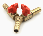
Im thinking of fitting a 3way Y fuel tap between the tank and the pump so i can:-
1. Turn off the tank while playing with the fuel system.
2. Drain the tank/system easily.
3. Connect to the drain and turn the tank Off so i can prime the pump.
-
I think the EFI has the flapper air meter. If so it could be jammed shut so you are only getting idle air flow. Should be able to remove it and clean out.
Could be the meter is not working electrically in which case it wont schedule the extra fuel so it would run lean. Might be able to clean up the contacts and wiper (inside not the connector pins),
Could also be the mice have eaten through the intake hose so its not sucking air through the meter at all.
-
Ok. Its acting as a switch to earth instead of going through the gauge.
But the separate circuits bit is not clear. In both methods both systems fail if there is no power from the delay unit. But yes you are right that they have separate outputs.
-
My understanding of how this works is as follows. The numbers are made up for the explanation as i have nothing to measure.
12v from the cluster goes through the delay unit heater coil (1 ohm resistance). Then down to the sender (1 terminal). This connects to the bottom of the sensor resistor. The top of the sensor resistor connects to earth via the terminal (2nd terminal) and to the body. Assuming the sensor resistor is 19 ohms then total resistance is 19+1=20ohms. 12v/20=0.6amps. The 0.6amps doesn't create a lot of heat on the warning light delay contact so the light is open circuit and off.
The wiper on the sensor resistor feeds through the 3rd terminal and to the fuel gauge. I will assume the gauge has a coil of 1 ohm resistance and then connects to earth at the cluster.
So when the tank is full, the float is high, the wiper is near the earth end of the sensor resistor. Not much change on the delay unit (low current lamp off), the sender output is close to earth so the gauge reads high (full).
When the tank is low, the float is low, the wiper is near the 12v end (from the delay unit). The circuit takes the path of lowest resistance so the 12v goes through the delay unit heater, then through the wiper to the gauge. So ignoring the minimal resistance of the sender resistor the resistance is 1+1=2ohms 12v/2 = 6amps. 6 amps through the delay unit makes the heater get hot and the bimetallic switch closes the circuit to the warning light (light comes on). Note the time delay while the heater warms the bimetallic strip - If the float rises again the heater goes off and the strip cools. So fuel slosh doesn't generate sufficient heat to warm the bimetallic strip.
So from the above:
If the delay unit goes open circuit (heater wire breaks) the warning light stays off but the gauge goes full.
If there is no earth on the fuel sender. The gauge shows empty and the warning light still works.
If there is a break in the sensor wire to the gauge. The gauge doesn't move and the warning light is always off.
The warning light switch level is a vague level based on the resistance in the system so quite variable from vehicle to vehicle due to tolerances.
I haven't looked at this for years but this is what i think happens. All 3 terminals are used.
-
RobH might be right. I don't have a circuit in front of me. Many of the circuits don't show the sender internals so its hard to tell. I still think its in series.
But i reiterate that its a delay unit not a relay. If you fit a relay the warning light would come on every time the sender float dropped. That's driving up hill and going round bends with about a quarter of a tank.
Some sources may list it as a relay if they are not clear how it works or the typist thought it was misspelt.
If you earth the signal to the gauge it should go full deflection.
-
Its not a relay - its the delay unit.
if memory serves:-
You should be able to jump the input (from the sender) to the gauge and get the gauge working. There will be a bit of an offset on the gauge due to not having the heater in the circuit. I don't know how much that effects it but its probably not much.
If the wire in the delay unit breaks then you will loose both indicators.
-
Hi.
My bracket that holds the fuse block doesn't align with the glove box. This is a RHD convertible. As far as i can tell my bracket has a another part welded on at the top that feels like it goes down the back, and has a stud that goes through the fire wall. Can someone confirm if thats correct. I haven't seen it in any pictures.
The fixings to the glove box then end up about 50mm right of the glove box holes.
Are there LHD and RHD brackets ?
I don't think you can fit the bracket upside down. Any one let me know what they have.
Because the stud aligns with the fire wall i cant adjust it. I will have to make an adaptor bar to support the back of the glove box.
I have also discovered that my instrument lights seem to be earthed through the metal brackets. Not sure if thats right but if you are having electrical issues its something to be aware of - metal canned relays etc may need the case earthed.
-
How are the guages not working?
Stuck low, stuck at max, incorrect reading but changes as you would expect. incorrect reading that doesn't change.
As Dave says the power is common across many gauges so unlikely to be the issue.
Im no expert but:-
The temp gauge suffers from:- No connection to the sensor (stuck cold), No power to the gauge (stuck cold), wrong sensor (changes with temperature but wrong values), Poor earth at the sensor (changes with temperature but wrong values), No earth at the sensor (stuck cold), short from gauge side of the sensor to earth (stuck hot).
Fuel gauge. Much more complicated as it includes the warning lamp delay unit. However if the gauge moves when the ignition is turned on its probably either an earth issue, stuck sender or fault with the warning lamp delay unit.
-
The rimmers site show these with some sort of structure inside the rails but it doesn't seem that anything attaches to them.
Could be for manufacturing purposes though it seems like over kill.
-
I can't remember the TR7 wiring but i don't think there is a main fuse. I think the power actually goes to the starter solenoid and then the wires come from there to the ignition etc.
So take a look at the solenoid connections. The solenoid doesn't need to work (it does to start the vehicle) its just where the wires come together. So if there is no connection at the solenoid nothing will work.
-
If it is only due to the turnbuckle I can only assume that its an earth issue and that now the pod is touching the metal bracket its creating a circuit. Doesn't make any sense to me as there seems to be plenty of other conductive routes. If you have the rubber stops on the bracket this shouldn't happen. Might be worth putting some tape over the stop points to ensure they are insulated and see if that cures it.
Since the pods are moving to different positions it may be that one has the lift arm fitted 180degrees out. Not sure how that affects the headlight but you don't know if someone tried to fix it by changing the wiring.
Hope we are helping. Atleast we are sharing the pain.
-
I had a weird issue when i replaced the main light switch. It doesn't sound the same as yours but be aware that the connector to the main switch can be fitted the wrong way round and give some peculiar combinations.
Are both pods up at the same time or do you mean when both lights are lit the RHS is up and the LHS is down?
Does the pod go up and down without stoping. If memory serves there is a 2 pole switch in the motor housing thats trigered in the up position to stop the motor. If this is faulty the motor keeps turning and goes back down. I think the other pole trigers on the down position. I believe these are pins on the motor connector as it feeds to the main light switch. If a couple of the terminals on the wiring connector are swaped you may have your problem. Im not the expert on this just trying to point you at a few areas to check.
-
Anyone know where i can get the flocked seal strip that goes between the door trim panel and the window on a DHC. This is the inside one not the rubber one on the outside. After hunting around for ages i have come to the conclusion its sold by the bog suppliers as part of the trim panel. I don't want to but a whole panel just for the seal strip. Im missing the RHS one and it means the glass rattles a bit.
Any alternatives or suggestions apreciated.
Regards
-
If we are speculating, they could be for seat belts.
I don't recall them on mine.
TR8 replacement radiator
in TR7/8 Forum
Posted
This is a TR7 with a 3.5L from an SD1 not a genuine TR8. Don't know if its a genuine TR8 rad fitted - probably not. Noticed that my radiator fins are rusting away in the bottom corner so thinking of a replacement. Searching for TR8 rads brings up options costing £400 etc. Ebay has Chinese Ally 3 core rads for as little as £185. While i am skeptical of these the price is less than half that of the alternatives. Any one got any experience. My rad is 40mm thick but these also have cores up to 65mm. Hard to see much difference to the performance radiators on offer.