


RobinTR
-
Content Count
95 -
Joined
-
Last visited
Content Type
Profiles
Forums
Calendar
Posts posted by RobinTR
-
-
I have just stripped down a TR6 PI engine and have found lock washers on the two bolts for Cap1, but not the other three caps. The BL TR6 Parts Catalogue has washer part WL0320 (8), which I assume means that there should be washers on all main cap bolts. Is this correct and I need to source a full set of lock washers, or are the bolts such that washers are not needed, for example single use stretch bolts? Same Parts catalogue shows bolts as HB 1024
-
Thanks, appreciate your advice
-
Hi Stuart
I have been planning to lead similar joints during my rebuild, but I have been concerned that the corrosive nature of the tinning paste would get into seam, where it would not be easily removed by usual washing and neutralisation steps, thereby creating a hidden corrosion pocket.
Can you give any recommendations as to how eliminate or minimise this risk of ongoing corrosion between the two layers of metal?
Where this is a new joint would you tin and neutralised the visible edge of both sides before spot welding and then complete the loading after?
Thanks, hope you pick this up despite the date of the original post
-
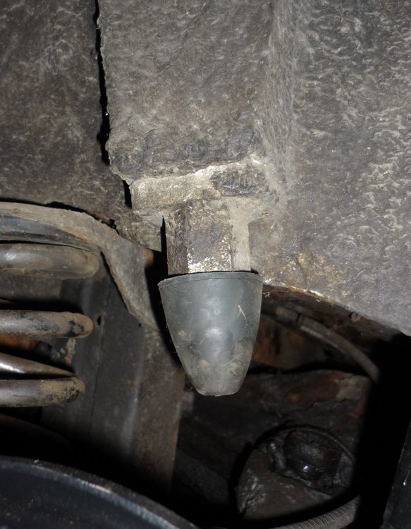
Jim, thanks for taking the time to send your measurements; it looks as though my bump stop is around 1" lower than yours. May explain why the rear of my car sounds as though it is bottoming out over even quite small bumps.
I will check around a few other cars to see what is going on... might be worth me trying to assess the distance between the trailing arm and the bump stop and also the fitted length of the spring
-
My 4A has: what looks like a rectangular spacer, a 30mm long hex block and the rubber bump stop. Overall length is 100mm from the body bracket to the tip of the bump stop. This seems longer than with the posted pictures, but has been like that since I acquired the car in 1978. What is the normal distance from bracket to the end of rubber stop, or any other distance I can check (for example protrusion below the chassis crossmember) ?
-
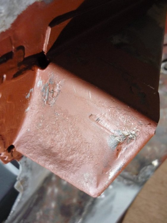
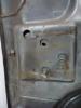
Dave, luckily no horrors on this part of my car... must be the only sound bit I have found!
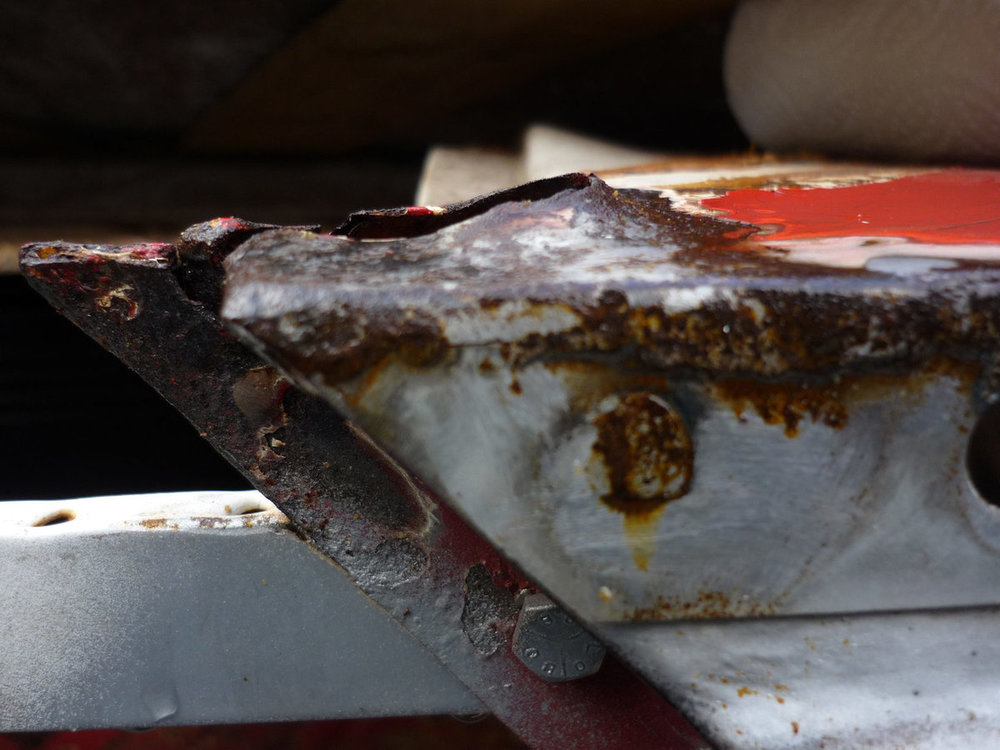
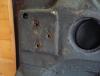
Visible corrosion was limited to some rust forcing one of the bottom plate tags away from the main bracket. As I am doing a "cut out all rust" restoration this tag was removed, revealing matching corrosion on the side of the bracket, so 15mm of this was trimmed away. This allowed me to look and feel around inside the bracket; I was very surprised to find only surface rust and no obvious thinning of the concave cap.
Will consider drilling a drain hole at the lowest point of the bracket, which might also allow for future wax injection
-
Thanks Stuart. Will check for corrosion and only repair if necessary
-
I suspect that the rear wheel arch mounted brackets can rot out from the inside, so was planning to remove, treat and replace the contact faces during my TR6 rebuild. However, the square shaped face is dished in, so please can someone advise if they started flat, but have dished as the result of repeated bump stop action, or if the originals did have concave faces?
-
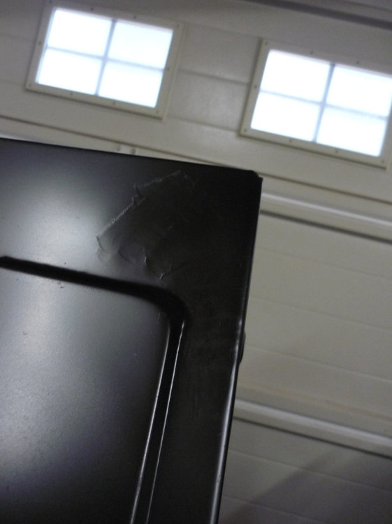
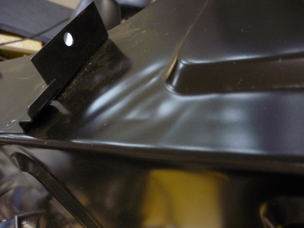
Refitting the reinforcement gussets at the base of the B-posts. Original reference points were absent, but looking at pictures of other cars it appears that the raised triangle part is in exactly the same plane as the flange for the door seal. Is this right, or is there a set distance between the plate and the flange to allow for the correct fitting of the seal?
-
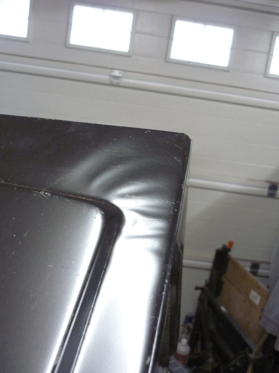
Five minutes with a shrinking disc has made a great improvement... now just needs a slight skim of filler. Note that paint will be fully stripped back before finishing
-
Hi Start, That is just the information I needed; a great help, thanks. I'll see what I can do to smooth things out a little
-
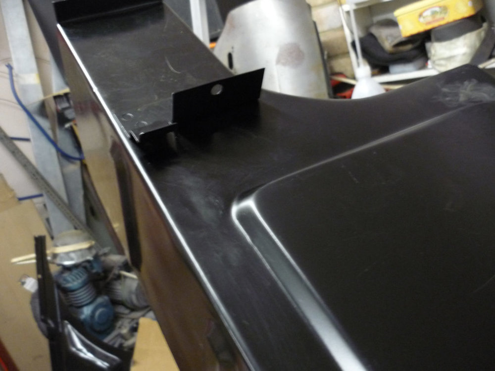
Hi Stuart, the floor structure was extensively over-plated sometime in the 1980's due to severe rusting. Now not possible to save with let-in patches, hence the two new Heritage panels.
Concours is not my aim, but I want to get as close to factory look as possible given the time I have already spent on the car. These ripples bug me, so I was thinking of working them out with a shrinking disc, or just dressing low, then applying a skim of filler.
Nothing of the original remains at these points, so I would appreciate any information/pictures indicating how these areas would have looked when new or after a good repair.
Pictures of the new floor panels are attached:
-
I will be facing the same dilemma soon. One thing I had planned was to mount the damper, rotate the crank and check the circumference with a dial test gauge to see if there is any run out. My engine was static for a long time, so I could imagine inconsistent swelling of the rubber if oil leaked to the low point.
Would appreciate any suggestions for a reliable replacement item
-
Looking for practical feedback on fitting Heritage boot floor panels (either side of the wheel-well) on a TR6. The pressings have ripples adjacent to the main raised section. Fitted panels were rusted and plated over years ago, so I cannot see if these ripples were present on the original floor, (like the ripples on the front wheel-arch), or only on these later panels. If not like the original, then can they be removed with hammer and dolly, or better to a disguise with a skim of body filler? Or do most folks just fit them as is and be grateful that these panels are still available?
-
Found the drive gear on the oil pump/distributor shaft is loose (rotates a few degrees). The gear for the PI metering unit is fine. I see the main suppliers still stock replacement Mills pins, so is this a common problem?
I assume that the pin should be driven out with a small punch (tapping on the end of the pin which still has a slightly conical end). I will try to support the gear to avoid damage, but any other advice?
Can I expect to find wear on the pin, or a slightly enlarged hole in the shaft? If the latter, then any suggestions as to how to remove the slop?
-
Thanks Stuart... your picture is a great help; I will repair to include a lip
Regarding "angles"; I should have been clearer and said the rake of the windscreen. Angle between door top and frame edge is 60 degrees on my TR4A, but more raked at 55 degrees on the template I made before dismantling the TR6. Window glass is packed away in boxes and the hood frame is not suitable as a reference. Was there any change in door glass and windscreen rake between the 4A and 6 or should they be identical ?
-
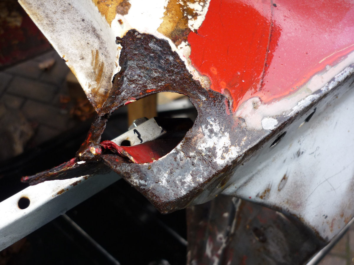
1) Need to repair the scuttle corners where the screen frame passes through a hole on each side. For a restoration on a TR6, should the hole be flat with the scuttle, or with a raised lip on the forward edge (like current rusty state)
2) I made a template off the screen frame before dismantling... it appears to be more angled than on my TR4A... is this correct for a 6?

-
Thanks Stuart. I may consider making up a slip plate to add a bit of strength, but fit this only after setting bonnet gaps.
I will be fitting a new BMH wheel arch on the side with the BL inner wing; I assume that this is fitted so that the whole of the fillet between flange and arch is visible when viewed from the inside. It just about does this without trimming the flange (although the flange is a bit wider towards the front of the wheel arch), but is my assumption correct?
-
Rebuilding TR6 which had poorly fitted replacement front inner wings (edge welded to wheel arch over remains of original inner wing). I will refit these as I think they could be original BL replacements (from details in the pressing and by comparison to a reference three-piece repro).
1) I found a historic posting on this forum where Stuart advised checking that the inner wing has reinforcement at the hinge mounting point. The repro panel has a fixed plate with captive nuts, but the "BL" just two 18mm dia holes (which put the hinge in a slightly different location to the repro). I think that the holes will allow additional movement for gap alignment... either with large plain washers as found, or I could fabricate a slip-plate with captive nuts to create additional stiffness.
2) The repro panel appears to be slightly longer than the "BL"; is it a known feature of the repro panels to be slightly longer than original? Any other differences?
Any thoughts on these two issues?
-
I have run several searches on the forum, but have not found the information, so I now ask about a pre-used replacement TR6 bonnet that has been chemically stripped to bare metal:
1) What is the recommendation to get some anti-rust protection between the inner support frame and the underside of the outer skin; paint somehow, or another other method after painting?
2) When new was there mastic or a rubber strip as cushion between the inner and outer elements, or just the primer paint on the individual parts? If factory applied cushion, then how to replicate?
3) Both original and replacement bonnets show indentation of the inner support frame at the hinge attachment; the stripped bonnet also has some stress cracking. I assume the weight of the bonnet and rough roads are to blame, maybe aggravated if the bonnet edge rubber wedges were missing?
Presumably this damage is common with this design, so other than welding up the cracks, is there any point trying to remove the indentation? For example: try to pull back to the original line (using lever device bolting to the captive plate), or beef-up by welding in thicker metal in this area, or simply add shims between the hinge and bonnet?
-
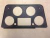
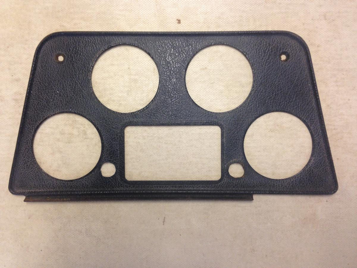
To my aesthetic view the panel would look better with a matching hole the other side of the rectangular cut-out.
So can you think of a second warning light as an addition to the overdrive? To my eye this would be preferable even if you have to resort to the blanking grommet.
Try playing with a photo editor to get a preview...
I have PhotoShopped an example:
-
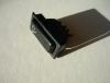
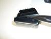
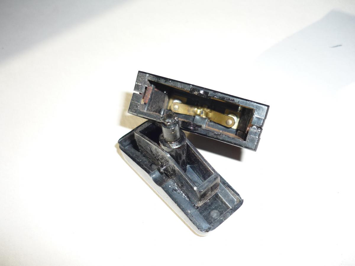
Dave, why do you need to refurbish your switch? Is it just cosmetic, or stiff in action... or are any of the terminals broken?
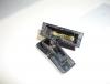
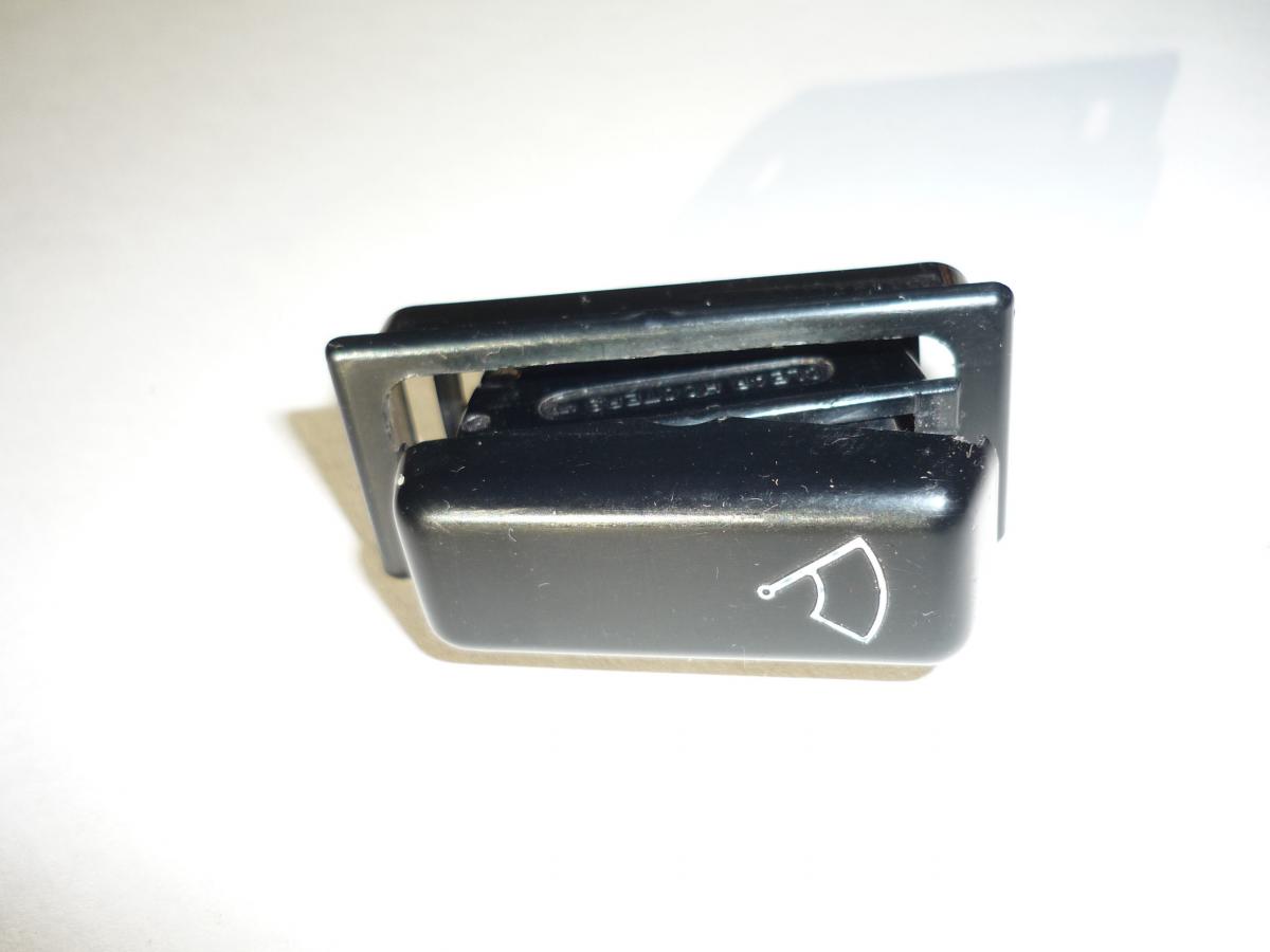
If just stiff, then it may be a simple repair as Steve says. Pictures show the wiper switch from my TR6, which I believe is the same as your part:
First remove the bezel... this should just push off
Use a thin screwdriver or blade to carefully ease the molded rocker pivot pins out of the switch body.
Check the action of the indent in the rocker and also that the pivoting electrical contacts look ok and pivot freely.
My contacts were ok, but the indent was stiff. I applied a little Vaseline to the indent and rocker pins and then reassembled. Switch is now fine, with definite three position action. If there is some resistance to the switch then try rotating the indent pin 45 degrees and check that the contact strip is central in the body
I did not have any problems with electrical contacts or terminals, but I am sue that a resolution could have been found if necessary
Note my picture of the Wiper Switch shows an incorrect reassembly; I believe that the top terminal should be 1, with 4 at the bottom

-
Thanks guys for the various suggestions
I was a regular user of Bonda Primer many years ago, so was intrigued to see that the product is still around for Stuart's recommendation. My only concern about this sort of "tough skin" treatment is wondering just how difficult it will be to later remove from the depth of the rust pits and pock marks? If it chemically combines with the iron oxide then this might make it resistant to subsequent treatment with acids formulated to dissolve rust. Maybe I will have to resort to localised shot-blasting for the final prep...
-
I have a TR6 stored outside under a tarpaulin awaiting home restoration. Some exterior panels have surface rust (and burrowing under paint), but these original panels are basically sound. I am getting back to bare metal with acid type rust removers and wire brushing , but surface rust is quickly returning.
Next year I hope to have more time available for tackling the surface pits using rust remover, wire brush, localised shot-blast, power sanding, primer etc., so I am looking for a temporary treatment which will prevent further deterioration, but which will not make this later work even more difficult.
Should I use: a recommended rust converter rather than remover, or zinc spray paint, or apply something like WD40 or grease? Unfortunately putting it in a humidity controlled garage is not an option!
What is suggested to put a hold on further deterioration until next year?


TR6 Main Bearing Cap Washers
in TR6 Forum
Posted
Thanks Guys... the bolts are 3", so presumably originally had lock washers, (still fitted to Cap 1, but maybe because they are located under the sealing-block). I need to check that there is no risk of bottoming out if the existing 3" bolts go back without washers
What is the story with the big-end cap bolts? The ones I removed are 3/8", but with a thinner "waist"; can they be reused ? Online searches show "waisted" bolts, which incorporate flanged heads but prices varying with supplier; there are also much more expensive "uprated" bolts. Any suggestions?