

spyder dryver
-
Content Count
56 -
Joined
-
Last visited
Content Type
Profiles
Forums
Calendar
Posts posted by spyder dryver
-
-
I've got one of these 360 cameras on my mountain bike. Cost me the princely sum of thirty quid. Brand new. If the footage is processed correctly prior to uploading it allows the viewer to change the viewpoint whilst watching the video. Just "drag" the image round with your mouse pointer or by fingertip if viewing on a smartphone. I found the processing part tricky and my uploaded footage loses quality. Here's some racing footage (not me) to show you what I mean. It's witchcraft I tell ye!
-
I fitted an aluminium flywheel during my recent engine build and came up against the "ring gear bevel" issue. I was using what was actually a front wheel drive engine and turning it through 90 degrees into RWD format. The RWD starter engages from the opposite side of the flywheel, so no bevel. As Graham H has already stated, you can't just turn the ring gear round so I hand ground a new set of bevels in the correct place. Not difficult at all, especially when you use a potter's wheel as a handy rotatable work surface! The amount of metal actually removed is miniscule.
The benefits of the light flywheel are greatest in first gear and diminish progressively from there. I had discussed the potential benefits with Peter Burgess and he said it would be really worthwhile. He said it shows up on the dyno.
-
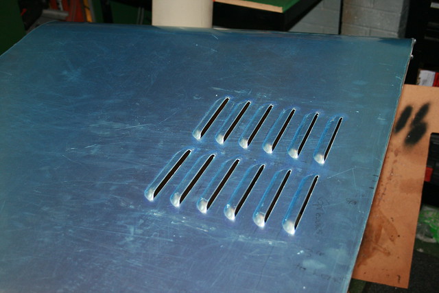
4 hours ago, Bfg said:
Geoff the new louvres look great, but do they not take air out of the engine bay, for that heat and possibly fumes to then be pushed down into the interior / heater system.?
I was advised, many years ago, while an apprentice designer, that engine bay vents immediately in front of the windscreen were a dangerous feature ..should there be a overheated water spurt / steam cloud, or oil an leak. Mind you "back in the day" it was not uncommon to hear or see evidence of an engine bay fire. I do recall seeing, back in 1980, an XJ Jaguar on fire, on the dual carriageway between Warwick and Coventry - That appeared fiercely hot.
I see your car also has what looks like extractor vents down the sides of the bonnet.
Pete
Hi Pete. I don't know if my car even qualifies as having an "interior" since it has very low cockpit sides, no doors and no roof. It's like sitting in a wind tunnel stuck on "Full". If there are any fumes being diverted my way I can't say I've really noticed too much and my brain is already addled anyway. Most kit cars of the "7" ilk have bonnet louvres like mine, Caterham included and they ( Caterham) have been through full manufacturer approval. Most of the others have been through the IVA test.
I'm sure that my car already had plenty of heat vents, including the OEM side vents you spotted. I added the bonnet louvres on aesthetic grounds.
I do "nod" to safety on occasion including fitting full "Schroth" 3" harnesses but the car itself would probably scrape an NCAP rating of -10. It has 200hp+ and weighs about the same as a classic Mini. If I really sat down and thought about it I wouldn't dare drive it at all, even slowly. The same reasoning applies to a lesser extent to TRs too. I guess it's risk versus reward at play.
-
-
All cranks are balanced from the factory, some likely better than others. During my recent engine build, a 1995 Toyota 3SGE 2 litre, I insisted on crank and flywheel balancing, despite being advised that it wasn't necessary. Guess what? It wasn't necessary! The crank came back with two tiny, tiny drilled dimples. One was little more than a dot punch mark. The flywheel had just one tiny dimple. A 60's crank may benefit though.
Bobweights are un-necessary on a inline 4 pot. Or an inline 6.
-
Hi Marco. I'd leave it to the experts. An incorrectly balanced crank/flywheel could easily wreck your engine. A detached flywheel could chop your feet off!
DIY balancing must be near enough impossible. I'd be amazed if it can successfully be done at all without proper professional equipment.
It doesn't add much to the overall cost of an engine rebuild either.
-
I have a 929 Fireblade engine in the garage, but it's in this...
Who can recognise the pilot?


-
In addition to the "matching pair" pitfall there is also the question of spares availability. Jets won't be a problem but some of the internals are size specific.
The ebay seller isn't too forthcoming with information, the most important aspect being choke size. 42s could be from 28 - 34mm as could 40s.
A road car may as well use 40s. Given the same size choke the actual advantage of the 42 will likely be un-noticeable. A well tuned car will probably be using 45s anyway.
The 42s seem to me to fall between two stools.
The importance of progression hole "correctness" cannot be over-stressed. A road car spends a lot of time in the progression phase.
-
Hi Graham,
is it an 'Interocitor'?
Roger
It doesn't look like one Roger. I'm building mine as a 2197 issue part-work. I started it in 1976. First issue 99p. I get the last issue next week! 13A plug. The newsagent has organised a streetparty and brass band.
Apparently you can now get one from Ikea.
-
Hi there. 40mm would be fine on a mildly tuned six. Even 38mm shouldn't pose any problems. A 40mm body is good for over 50 hp on a 500cc cylinder according to many a calculator.
-
Spyder can you explain a little more please? D you simply give the pump a double feed so that when the fans hit the pump got the extra current?
I am thinking of only feeding via fans so that extra pump only comes in when fans are going as generally when driving my fans dont run only when idling and when stopped. Also did you need a relay for pump or was it enough to just feed 12 volts?
Tony
Hi Tony. You are essentially correct. Two feeds to the pump. One from ignition via a resistor, the other from the fan circuit. Relays to both feeds. Standard thermostat in place.
As already stated, the mechanical pump may not like another pump in line with it, running or not. I think that water will pass through a non-running Davies Craig pump but any restriction could be bad news.
If you intend to keep the original pump running then maybe look at the auxiliary pumps fitted to many modern cars. They should have been designed to allow through flow.
-
I fitted a Davies Craig EWP80 to a Lotus twincam engined Westfield to replace the troublesome original. I tested the pump in a bucket and was amazed at the flow rate. I fitted a power resistor in the 12v line to reduce the flow to around half. Full flow ( resistor bypass ) was triggered by the electric fan thermo switch which was a Kenlowe type bulb in the top hose. This meant that if the fan stayed on when the engine was switched off then so did the pump. No other controller was necessary.
-
If they weren't trying to pass it off as a TR5 they wouldn't have bothered hoodwinking the DVLA.
They wouldn't have put TR5 badges on it.
They wouldn't be asking £42K.
The kit car market is similarly infected with ne'er-do-wells usually selling newish builds complete
with old kit car V5s or an old "donor vehicle" V5. There was an amnesty twenty years ago which allowed corrections to the paperwork but nowadays the DVLA are not so easy going.***
They usually get flagged up on the forums but the attitude of many posters is " who cares?"
I despair.
*** Unless its a TR250/TR5 it seems.
-
Couldn't the Register approach the DVLA or Trading Standards with specific reference to this car?
Or the Police even?
Does the website have a history of this kind of shenanigans?
IANAL but it looks like fraud to me.
-
Hi Andrew. I look forward to seeing your car on Sunday. I have done an EFI install on my car using GSXR750 42mm throttle bodies and Megasquirt MS2. Early GSXR bodies can easily be re-spaced to suit and the Megasquirt ECU can be self mapped using TunerStudio software. The difference it made on my car was well worth the effort. 16-20 ft.lbs right across the range together with "closed loop" control of AFR during cruise.
See you Sunday.
-
I'm in the process of buying a pair of vernier pulleys for my ongoing Toyota engine build. The marketplace is polarised between cheap Chinese and expensive Japanese or American at 5 times the price. On the net I have found two horror stories where the bolts had come loose and one of accelerated wear due to them being alloy in place of steel. All three involved premium price items from the most well known and respected names.
Now maybe there are just more of the expensive ones about it leaves one in a quandary. I'm fitting high lift cams with uprated springs and revving to 7500 (maybe more) The load on those little bolts doesn't bear thinking about!
Some pulleys only have three clamping bolts, others five.
I think I'll go for five.
-
The restriction and consequent power loss caused by gauze is well known and should have been pointed out by the rolling road operator before he started. If the change is that obvious when they are removed then you are leaving a chunk of power on the table by leaving them on.
The Kastner trumpets above look good.
I was just about to post the same Vizard link as above. You beat me to it!
-
Done a bit more investigation myself. Yes there's a theoretical CR based on the geometry/size and an effective CR which is lower than the geometric one. The difference being the volumetric efficiency.
Its less to do with VE and more to do with inlet valve closing angle. IVC. No compression can occur before the valve is fully closed. This happens at some angle after BDC and can be well after BDC. This angle on my 16V engine is 65 deg ABDC. This means that the piston is part way up the bore and that distance is further affected by conrod length. I have measured this effective stroke on my part built engine and it is 61.5mm. The stroke is 86mm.
By then using 61.5mm in the normal calculation it gives a "dynamic compression ratio" of 8.2
Dynamic comp ratio, DCR, is a "big thing" in American V8 circles. Less so over here. Google it.
I was at Peter Burgess' with Mick today. Pete has never calculated DCR.
As regards calculating comp ratio from compression readings this all means that you are actually trying to calculate the DCR.
In the previous post DDR has seemingly found out that the DCR of his engine is 81% of 9.5.
If you stand this on its head it seems that the piston might be roughly 19% on its way up when the valve closes. It might be possible then, if you know the closing angle and conrod length to derive the static comp ratio.
Or thereabouts.
Well nearly.
The main spanner in the works will be the inevitable heating that occurs during compression. This imponderable alone is enough to scupper what may have been a meaningful exercise.
There are various DCR and static comp ratio calculators online. I have just burretted my chambers as well as measured the ccs of piston dome.
Its the only way to be sure.
-
-
-
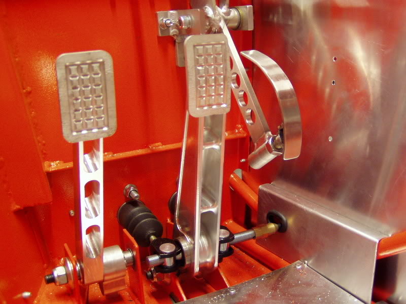
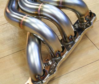
This is my trackday car manifold...

-
Posh? Well... you might be right. These aren't mine. Dare I say it... mine are wrapped.
-
Nice work. Now all you have to do is polish them, then weld them using an extra internal purge.
And simply bash a dent where it touches the frame. It won't make much difference to the flow.
When I made my own I arranged it such that each section slipped inside the next. No butt welds and it held itself in shape. It helped that the port end was 1 3/4" and the collector was 2".
-
Result showed the car was thirty five kilos lighter OS front compared with NS front. OS front spring was shimmed (3mm I think) to achieve equal front wheel weighting. Car then sits on all four wheels with equal weights.
That's not usually how it works, Alan. Actual wheel weights will seldom be the same. Look at Hamish's quoted wheel weights. Nearly a fifty kilo spread. Now go online and punch the numbers into one of the many available online corner weight calculators. In terms of what matters the results are very good. It's all rather counter-intuitive and impossible to sum up in a single post even if I could.
Which I can't.
I seem to remember going through this exercise many, many moons ago along with Mick on the TR7V8. We didn't have corner scales. We had a lever device that lifted the wheel rim and gave a reading on a scale. The readings were seemingly a bit various until we worked things out on paper. No online trickery in those days! Results were within a few percent of ideal so I think we just left things alone.
And in relation to the OPs question...
I can't believe that we have a thread discussing TR handling and no-one has mentioned bump steer!
Tell him Mick!!


Spot & Fog Lamps
in General TR Technical
Posted · Edited by spyder dryver
From the MOT manual...
You only need to inspect:
front fog lamps fitted to vehicles first used on or after 1 March 2018
the 1 rear fog lamp which must be fitted to the centre or offside of vehicles first used on or after 1 April 1980
This would suggest that any fog light fitted to any TR older than 1980 should not be inspected.
As regards a single front "spot lamp" I can't see any direct reference.
The manual seems to suggest that only "obligatory" lights are tested and the additional single lamp would not be included.
Vehicle lighting regs may well be different. The above only applies to the MOT test.