


Trumpy3
-
Content Count
121 -
Joined
-
Last visited
Content Type
Profiles
Forums
Calendar
Posts posted by Trumpy3
-
-
I use Locktite No3 on all standard gaskets except for timing cover(Chest), sump, and rocker cover. On the sump and timing cover I use a shin smear of RTV on either side of the gasket. With the rocker I place a smear of RTV on the cover and stick the cover to it then place it face down on a flat surface with a weight on it and leave overnight to dry. This allows you to remove and replace the cover numerous time without needing to replace the gasket. With an alloy cover it is really great. I have not had to replace mine for over three years, even after I changed the cam.
As a matter of interest, always use a sump gasket. I have found, by experience, that the crank/con rods will hit the baffle plate in the sump if you do not. If you do not believe it, I didn't, fit the sump without a gasket and fix it down with a couple of cap screws and turn the crank. Its a close tolerance.
Brian
-
John
Fitting a smaller wheel is easy, just buy a wheel and hub. The horn and indicators are the issue and can be attacked in different ways. Like others I fitted a Triumph Saloon(2500) indicator stalk which fixed horn,indicators, dip switch and allowed headlight flashing. There are many other solutions which I have read on this forum. Each one with its own issues.
If you have standard steering set up then you will find the steering very heavy, heavier than standard, depending on the wheel size.
Brian
-
Ooops. If pulley fitted incorrectly, the timing mark will be out AT LEAST 60 deg.
Brian
-
Devs
If you have good fuel in the carbs then he cause is almost certainly ignition, as others have indicated. The best way, I have found, is to first check you have spark then check the timing. Checking for spark is easy and I am sure you have done so. I find a timing light the best and quickest toll and not expensive. All you need to do is hook it up and see if it flashes when you try to start the engine. If no spark, fix the problem. If you have spark then timing is the most probable.
Check your timing. Pull no 1 plug and get the engine with No 1 piston at the top of its stroke and both valves closed ( loose rockers). The TDC pointer should be somewhere near the mark on the pulley. Remember if the pulley is fitted incorrectly the mark will be out by around 60 deg so it should be obvious. If incorrect, then fix that.
You should now have fuel, spark, compression.....then engine should start. That is of course providing you do not have some other issue which I doubt.
Good luck although its not luck you need, it is simply a plan and logical process.
NB. You have rebuilt the engine. If the cam was out or timing chain replaced, is the valve timing correct. You are getting compression so it is most likely OK but I have found engine cams timed on No1 exhaust, not No1 inlet.
Brian
-
There are units with a remote operating face where the main unit is positioned remotely, out of site. The face can then be attached to a fitting so it can be folded up behind the dash and out of site.
Brian
-
Just checked the book. It shows them to be fitted to the rear.
Brian
-
Good question. I have always fitted the plunger to the rear.
Brian
-
Regarding a collision switch, a number of members here use a switch from a LPG car system. They are relatively cheep and reliable, although you only find out it does not work when its to late.
Brian
-
Rear seal will not always show from the bell housing. Most oil leaks from the rear of the engine, I have found, show around the plate fixed to the front of the bell housing at the back of the sump. Leaks can come from rear oil seal, around the rear main bearing cap, cam welsh plug, main oil gallery blanking plug as well as leaks from all over the engine as the oil always seems to get the the back of the sump.
I suspect a lot of rear crank seal leaks are in fact from around the read main bearing cap. This has been my experience. To properly check that you need to remove gearbox and flywheel, thoroughly clean around the rear of the engine, refit the flywheel and starter, support the back of the engine, start the engine and run for 10 to 15 mins. Remove flywheel and look. any leaks should make a showing. If the rear cap is the problem it can be fixed in chassis.
Remember, if parking facing uphill, some oil will always leak from the rear seal when the engine is shut down. It is only residual oil around the seal. Once the engine starts, the oil scroll will prevent leaks. I know this because it had me excluded from a hill climb because of a leak while stationary in the queue waiting my turn. Returned to the pits, placed a piece of rag between the sump and bell housing, returned to the queue and enjoyed my run up the Bathurst climb.
Brian
-
Every time the radiator cap is removed/refitted, the top Tank/extension is placed under stress. Removal of this stress is a plus as is the reduction of the concentration of the cooling fluid caused by the top ups.
Brian
-
Bob
Spot on.
Brian
-
HI.
I know this is an old thread but would like to add a comment. I have had some experience with the design and operation of modern cooling systems. I'm no expert but have enough knowledge to be a little dangerous.
The early "overflow" bottles are in fact recovery bottles. They were introduced to reduce the need to remove the rad cap to check the coolant level and retain the concentration of coolant additives ( antifreeze and corrosion protection). They require a recovery cap to work. These are caps with a top seal to prevent the coolant from spilling past the cap was engine heats up. In Australia, these are hard to find for a long neck cap as fitted to the early TRs. The line from the radiator must run to the bottom of the recovery bottle.
As the name suggest, the coolant flowing to the recovery bottle is returned to the radiator as the system cools via the low pressure valve in the radiator cap. This is why you must use a recovery cap with this type of system. All this ensures that no coolant is dumped during warm up but simply recycled. The bottles are see through so the coolant level can be checked without the need remove the cap. This is particularly advantageous with the TR as there is no need to stress the top tank extension which leads to a lot of radiator leaks.
The latest systems were introduced because of the intricacies of the modern systems with heating and cooling pipes going every where and the common use of cross flow radiators. Apart from coolant recovery, it also adds a self bleeding function with return bleeds from high points in the system. For this system to work the recovery bottle must be more robust and pressurized. As such it houses the pressure cap.
I use a Volvo 240 radiator on my 3A, and a latter Volvo recovery bottle with a 10psi cap. Never need to remove the cap and the coolant is not diluted with continuous top up. This has been in use now for some 14 years and included around 6 years of track work.
Brian
-
I turned up an aluminum elbow with an O ring to fit inside the block. It has a small flange on the outer surface against the block. I then taped a small (3mm) thread next to the block breather hole and after fitting the new elbow screwed in a short screw with a washer that worked with the flange to prevent the elbow coming out. The elbow was then secure but could be turned to any direction required. This has been in place for about 12 years now.
I did this with the engine out so would be a bit hard with it installed. It may be a bit to understand exactly what I done from this description but I am down at the Melbourne F1 so cant take any pictures.
Brian
-
My betting is on the raised lip on the scuttle. I use a strip of small edge trim on the lip about 2 feet long to quieten mine.
Brian
-
A quick addition to the above. You do not need the gearbox to be removed to fix the starter mounting nut, just the transmission tunnel.
Brian
-
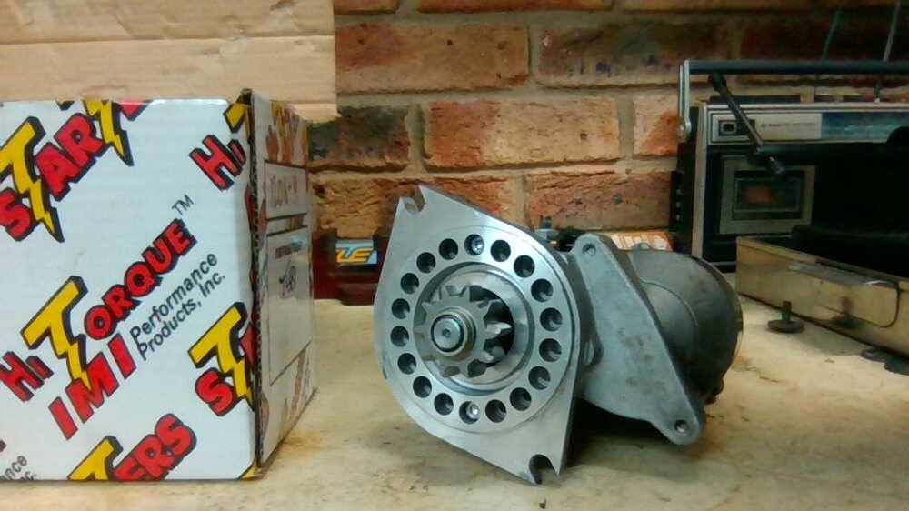
I have had to repair a few of these, two for myself and a few for other members and one Toyota. I have found two problems. Burnt contacts and broken wires where the coil windings are soldered the plate that connects them to the solenoid contacts.
The broken wires can be first by soldering them back on. The contacts can be replaced as noted in the previous post. Burnt contacts are the most common. I have found the the contact kit that includes the armature is the best,\. The armature is the part that is sometimes called the plunger.
It is important that the contacts remain flat in the solenoid to ensure a full contact with the armature. To do this I loosely assemble the contacts, insert the armature and place a suitable sized spacer (piece of wood, nut, etc) on top of the solenoid and fit the solenoid cover so that it holds the armature down firm on the contacts. Then tighten the contact mounting nuts. Remove the spacer and refit the cover.
As a matter of interest, the starters we use here do not have a stud for mounting. It uses two nut and bolts. I make up a small metal tag that is clamped under the gearbox mounting bolt immediately above the top starter mount and extends down and under this top starter mount. I then tack (weld) this to the starter mounting nut. This keeps the nut in place when removing the starter. Of course this has to be done with the gearbox removed. It is matter of taking the opportunity when and if you remove the gearbox.
-
Mmmmmm. Sounds like head gasket.
-
Bob
Re the cost of shims. From my recollection, one shim covers both mounting bolts. Hardened washers should be OK if needed. I have 4 spot aluminum Nissan Skyline calipers with a custom made mount. My original disc was a re drilled Chrysler Voyager unit ( same offset and diam as TR unit). This was fitted back in 2001 but since 2014 re-drilling disc became illegal here so needed to find an option. The only ventilated disc I could find (I need 25mm thickness) was the disc supplied by Moss in there upgrade kit. The only issue was a 3mm difference in offset. That was overcame with 3mm hardened washers.
I have done over 30000km since and no issues. As a matter of interest, there was a loss of braking effort with the new disk (material? they are Chinese). I had to replace my harder TRW pads to a softer road pad.
Brian
-
One good thing about driving to the track is that you get everything closer to optimum. Down side is that it is uncomfortable with four race wheels in with you.
Re the IR gun, I paint a small flat black spot on the thermostat housing to get a reliable reading.
Brian
-
Acid bath!!!! You may need to replace the aluminum plug in the top of the head. People forget about that one and regret it when the head has to come off again, some time a while later.
Brian
-
That's not a very nice looking crank. What is all that discoloration? I thought that only No1 rod bearing failed? I would be reluctant to use that crank without some testing and certainly not the rod.
With only that photo to go by, it looks like lack of oil was the cause of failure and No1 was the first to completely fail. Looking back over your previous input on the subject, did the rod bearing suffer from low oil pressure and finally fail after your attempt to rectify the low pressure? I'm not a big believer in coincidences. It looks to me with the information at hand that your issue started with the rebuild and ended with the rod bearing failure.
Brian
-
I'm a fan of removing the crank gallery plugs. The one concerned with no1 rod should be checked at least. As there was no damage to the main bearings there is a good chance that the crank galleries are clean. Your decision. That is one of the major problems with not knowing what was the cause of the initial failure.
The crank tends to act as a centrifuge and heavy (metal/dirt) particles end up pressed against the plugs. It is this that we clean by removing the plugs. If No1 rod bearing failed due to debris trapped during the first build in the crank ???????
Brian
-
+1
-
Graham
How you going with that engine?
Brian

Cold starting and warm up TR3A
in TR2/3/3A/3B Forum
Posted
Paul
Sounds a bit like no choke to me. As others have suggested, check to ensure the choke is actually working when you pull the knob. It is not at all uncommon for there to be no or very little choke applied even though the knob is pulled. Normally this is caused by the settings on the linkages or cable pulling through the fitting on the choke leaver.
Brian