


TriumphV8
-
Content Count
1,358 -
Joined
-
Last visited
Content Type
Profiles
Forums
Calendar
Posts posted by TriumphV8
-
-
There are so many systems in the market that you can not say this will work and that will not.
First the diameter of the bearing has influence. The larger the diameter the more the spring ist compressed.
Our hydraulic throwout has an individual working areas different from the normal 1" slave original.
The harder the spring the more the original construction will suffer due to friction in several areas. So the centre lockout plays out its advantages especially with performance clutches.
I had several master cylinder at hand and simply tried out what can be used that clutch will properly disengage. It was the 0.625"
-
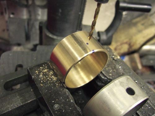
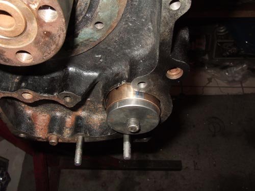
Back to the cam bearings:
Here are some photos of my work.
Bearings are from CuSn12
puller made to bring them absolutely straight into the block
with proper position of oil holes
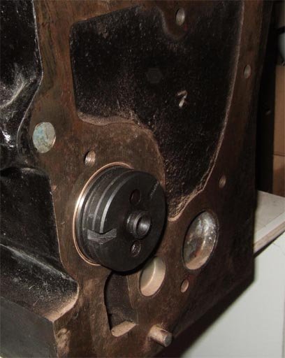
and last picture with cam in the block ready to use
-
A good choice! We do so, too (similar Z320 recommendations)
Slippery clutch is nasty!
-
Things are pretty easy:
If you do not have the tools use some tricks.
I would buy the recommended coil from simonbbc with 3 ohms.
Connect it to the wiring as it should be, make a connection from the point side of coil to minus.
Measure voltage at the plus side of the coil against minus.
Put ignition on and read:
If you have 12volts you have non resistor, if it is reading six than the voltage is split between
the coil and the ballast wire, so you have a resistor in the wire somewhere.
All coil switching on and of produces a spark, so be carefull.
-
It is the question how precise it must be. If you are on PI you are often on the rich side with AFR setting, so metering a bit not precise will not do any harm.
With our EFI we want to go lean close to the limit and can not tolerate any difference in airflow to each cylinder. That ist why modern throttle bodies for bikes and sports cars are made with watch precision.
If the linkage does not move when nuts are fixed something ist not in line. Make a precision shaft and try to fix outer holders and bearings without linkage. Try than to move the shaft through the outer bearing to meet the inner bearing.
If it does not slide in than bent the outer holder until it does and so the same procedure at other side.
I used the needle bearings because they do not stick that easy.
I cut the shaft for the middle bearing because I found precision not that precise with only two bearings. Must have been the same conclusion like Triumph had in the past. Simply make a precise tube over separated shaft, outer side welded, inner bolted with a screw.
-
Hi, the shells are from Spitfire 1500, who used them for a limited time.
Clearance ist 0,03mm or a bit more.
I did the drilling by myself in an old milling machine and found it necessary to drill all bores in one step and have a support at the clutch side.
-
37 minutes ago, RogerH said:
Capacitors are also affected by vibration. A good many Hi-Fi nerds will stick 'BluTak' to the capacitors to stop them vibrating..
In theory this will clean up the signal.
Roger
Coils, too. In Germany we have Mundorf Company who does a lot of crazy things to speaker networks. The wire in the coils have tendencies to vibrate and are glued together in a special manner. Would be a good idea to let all these details influence our ignition systems as long as this keeps nearly invisible. Hifi and Oldie have both in commen that all works and it is difficult to judge if it can do better.
-
On 12/8/2020 at 7:36 AM, Z320 said:
Fred,
it was in my mind to ask today if anyone really drove his car without condenser,
because that's what I also found at the literature (not at the internet), but I'm to often the killjoy here:
the spark will be very week and the engine will probably not run.
The reason is the coil wants to keep the current after the contact braker has opened,
but a strong spark needs a as fast as possible changing field (to zero) and therefore as fast as possible no current anymore.
Back to the topic I can say that all condensors are not the same and all transisitors not, too.
I came up to the capacitor problem by Hifi where interesting caps with silver gold sheets are used. They reduce resistance significantly.
A cap in reality is a cap plus a resistor in line what never interested me before, until I came up to the problem because we learned that our MegaSquirt delivered different spark lengths with identical coils. We have an old Bosch Tester to pull the spark length until it fails.
Fitted are the TO220 shape transistors where the BOSCH type BIP373 is very famous. Meanwhile it is superseeded by the IRGB14C40L. Unfortunately I fitted a third type that gave a spark, was reliable but the spark was weak, causing problems on start on and maybe powerloss on high revs. It did not open fast enough.
Although I did not test it, I would expect a weaker spark with an old cap where the inner resistance rises by nature causing a not so steep rising of voltage curve. It is difficult to judge from the outside if the equipment fitted gives the best spark possible and from that I would try to fit the best I can buy. On the TR4 that might be of less interest because there is not the need of a fast spark delivery but the TR6 needs a very good spark system.
With the normal ignition setup we triggered the spark by MegaSquirt and played with the time the points are closed to "load" the coil. It is called the dwell time. Depending on the coil this varies from 1 to 10ms where normally 2-4ms is normal with sports coil 3 ohms. What we found out is that required dwell time to avoid misfire at high revs is pretty close to the time that is availiable between two cylinders firing. The conclusion is that TR6 normal points ignition must have a sports coil like the red BOCH and must be in best shape not to cause powerloss.
-
23 hours ago, john.r.davies said:
No argument with the statements above, but I'd love to know where they come from/their authority.
TV8 - "the inlet liners the speed should be limited to 80m/sec."
and
trolleybus: "The volume of the plenum should be 85% of the swept volume of the engine"
Can you provide references, please? Books, papers?
Hi John some of my knowledge is from Apfelbeck/Wege zum..... and H.Hütten/Schnelle Motoren.... and H.Hütten/Motoren.
Would recommend Apfelbeck to everybody who is interested in tuning because he is a guy that does the job with a pretty low machine equipment, that mostly can be arranged at home. Always with the approach as good as possible but also as cheap and easy to reproduce as possible with the help of some good ideas.
-
If I do my calculation correctly we will have around 6000 litres air intake because we do not not fill 100% at high revs.
The inlet area with 5" will give 121cm² and with a rate of 100 litres per second it will be only 9m/sec airspeed.
That is pretty low, in the inlet liners the speed should be limited to 80m/sec.
So I would be interested to see if just the increase of diametre from a quite low flow rate before will increase power.
I found out removing air filter box will lean engine and so wil increase power if properly set but copy this air box is a lot of work and it would be nice to see before if that makes additional sense.
-
I do not like the rope trick, although it will not do any harm in most cases.
But..... you put pressure on the rod without oil in the bearing, what also may be okay, because some oil maybe left after runing last time
and..... it is not similar to the combustion because the force is only that much as the torque around 20mkg at the crank. with the combustion the piston can move downwards to compensate the higher pressuere while burning. Must be much more complicated to calculate that but I would not torque the crank with piston half way up more than 20mkg.
My idea would be to make a platform sitting on all of the studs providing holes where the bolts for the posts of the rockers are. Remove the bolts, set threaded bars of proper length and torque them all step by step and I am sure no head can resist!
-
4 hours ago, JochemsTR said:
So to summarize:
A-Type OD and non-OD: removing towards the front.
J-Type OD: removing towards the aft, with removing the diff in most cases necessary.
Korrekt?
Jochem
I think not
I have a TR6 J-OD with a lot of trouble with prop from Revington. In short the old had vibrations and after changing U-joint still persist and the high performance new item from Rev failed two times. So I am familiar with removing and all without touching the diff. As far as I can see my frame is stock and although there is not much space left the prop comes out to the front.
My V8 also had several props but I have the Rover gearbox at the front. Flange is same position as Triumph gearbox and here I had two props with much larger diameter at the tubes and they still come out.
I would expect little differences in the frame or engine mounting if some have trouble and some have not. It is not gearbox related.
I did see some people can change the front belt and some have problems to pass between engine and tube. These also might have difficulties with the prop because engine is a little bit more located to rear.
-
Elmeso Reban in Germany does the large bore gasket.
Also the cheap silver gasket from Rimmer does the job, but always the block must not have the recess. It can be milled off by taking about 0.7mm away if its a recess block.
I found the VW and MAZDA piston availiable and found a company who does the drilling. They meanwhile made about half a dozen 77mm bores and one 78mm.
So the VW piston in 76.5mm or 77mm is my choice not only for the 5HP it will give, but also the block becomes 4kg lighter.
Both pistons MAZDA and VW are very good quality and are pretty cheap.
Things should not be made more complicated than necessary......
By the way: Triumph sometimes did lining of the blocks and for that the drilling is done to about 77.75 and the liner is pressed in. So that is what the block can handle.
-
1 hour ago, JochemsTR said:
so Class 10.9 with 150.000 psi or Grade 8 with 150.000 psi is the correct bolt to use?
In some tuning sets you find normal Grade5 bolts in longer version.
I wanted to be on the save side that is why I took Grade8.
-
I do not notice any difference when swapping to heavier discs.
Later I swapped from heavy wire wheels to Alloys with no difference.
Right now the V8 has really heavy wires in 7x16 with 215/55 and spanner with 3 ears.
That is also with the Bilstein setup far, far better than original and somewhat better than Spax.
It is far more important to have big valves in the shocks to open quickly on bumps not bringing
the whole car in motion and damp things down quickly.
-
I removed the original Grade5 bolts and used Grade8 bolts.
We have a very good supplier, Screwcorner, here in Germany.
The longer bolts to hold the brake pads are normal steel.
The spacers are made from steel for Harald and EN7075 or steel for me.
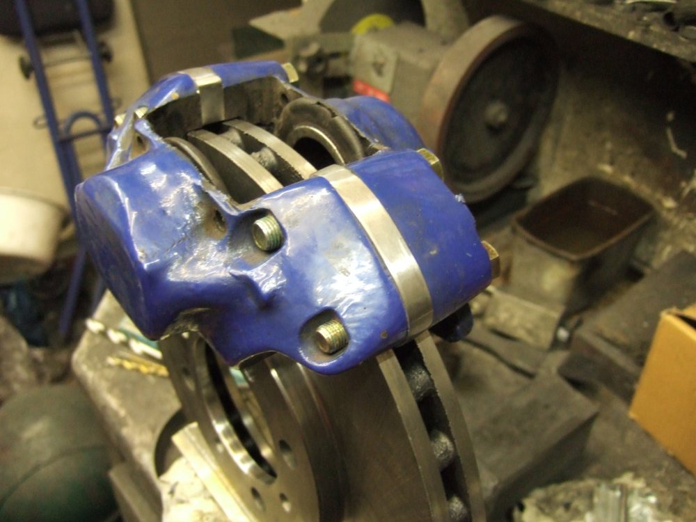
We have the EBC set as a template and cut them out of a flat bar.
We made the fluid pass individually not using the template
because we learned that the holes sometimes do not cover the canal gasket.
-
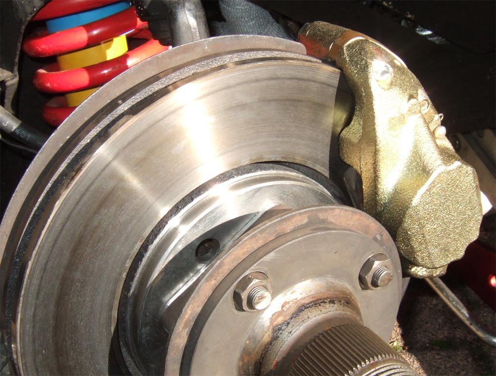
14 hours ago, Z320 said:
4 "washers" each disc or a spacer ring with 4 drills?

Between the flange and the disc you see the shim.
It is a single plate right there shiny but meanwhile as rusty as the flange.
I made 10 of them, welded them together at the edges, put them in the lathe and made the inner bore. Than grinded of the edges to get the round corners, put them on the flange and marked the positions of the four holes and drilled them.
-
On 10/25/2020 at 12:28 PM, Waldi said:
Note in Jochems picture the EBC disks are 4 mm (!) thinner (20 vs 24 mm); It can only mean less cooling or less “meat”.
Waldi
I think they are made that thin that some steel wheels fit with that swap.
The wider the disc the more the caliper comes to outside.
So mine is 4mm more to outside, too much for steel wheels.
My brake interfears between steel wheel and caliper.
Anyway a friend had the EBC set and also did not clear the caliper but has wire wheels now.
The worst in my opinion are the dimples in the disc that make noise and show from outside that there is something special.
One original EBC set had the holes for the brake fluid not in perfect position for the caliper.
The canal gasket sits in the bore of the caliper making fluid drop out.
I had to make four new spacers.
-
On 10/25/2020 at 12:36 PM, Z320 said:
Hi Andreas,
with the Ford Sierra discs you need to make a distance shim?
Or is this not the case?
Yes, 2.5mm spacer and so still the centering of the hub can be used.
A simple shim cut out of a steel plate
-
Why that complicated?
meanwhile about 10cars adapted my use of the Cosworth discs.
They are 4 hole and do not look that ugly when redrilled.
For centering I have a very simple tool:
I made an emergency wheel from Volvo with 114,3 x4 circle and
did a fine job with my finebalancer to balance at the car.
Swapping the wheel into several positions you find it properly balanced.
Than you fit the new disc to the flange and to the car, fit the wheel and balance.
Difference is not to put weight to the wheel but cut material from the disc with a grinder if necessary.
Not that necessary and in most cases not that amount but as it is easy done I grind it to perfection.
-
I have some blocks from steel for the front made from a clubmate.
Jigsaw does them also for a good price.
That stiffens the front block and allen heads can be used for proper fixing.
If old block needs new thread be aware that the debris may pop into the engine
although most will pop out from gravitation.
-
Connect MS to the stim and set the stepper fully open 256 steps at 20 degree engine temp and fully closed at 90 degree engine temp
with the laptop.
If you like make a gauge with the steps from 0 to 256 and a water temp gauge if not already on the dash.
Now you can play with the wires changing water temp at the stim an find the proper connections. It was quite easy when I did so some years ago
-
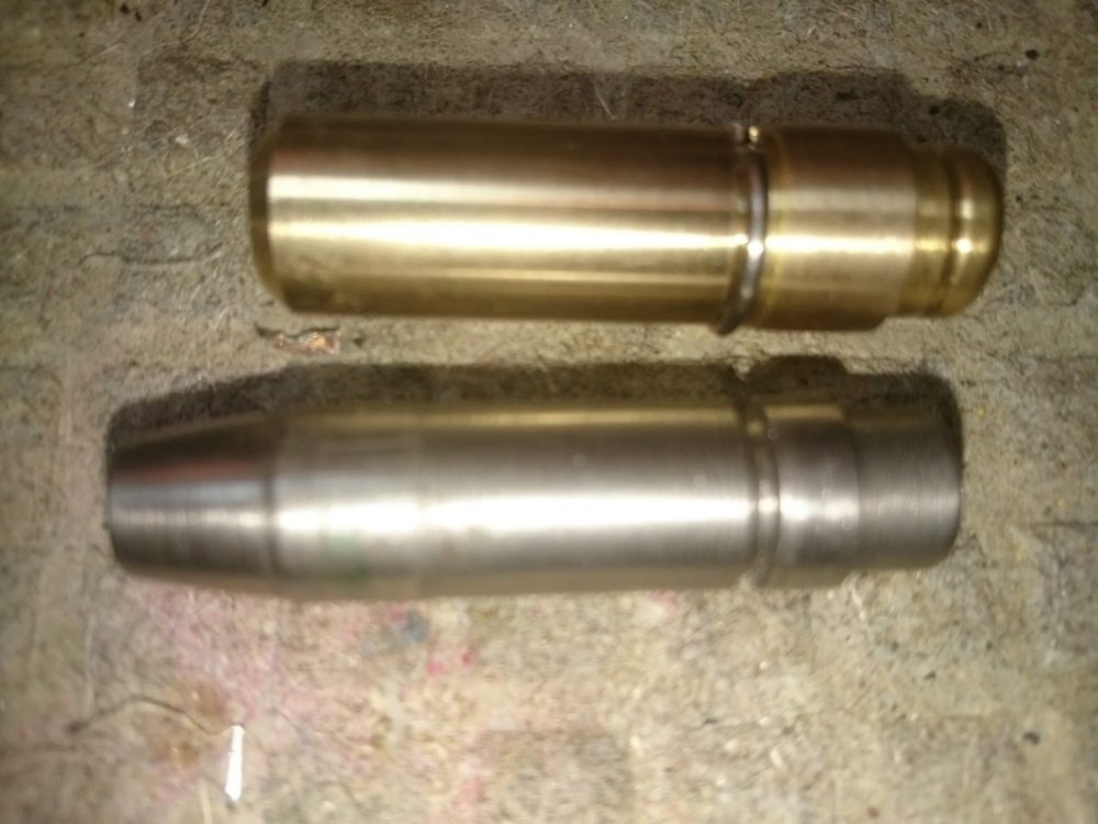
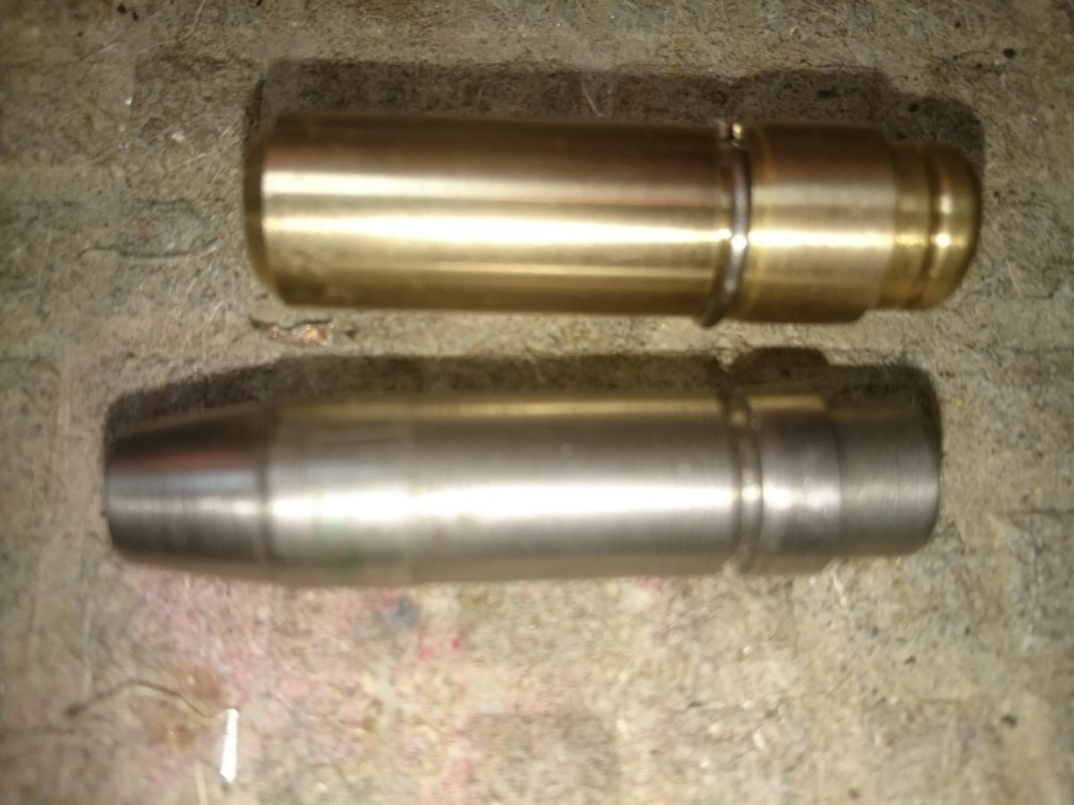
As Jochem told, one is for exhaust and one for inlet.
Unfortunately the camshaft and the rocker ratio must be taken into account.
Hi valve lift requires shorter guides.
If the guides are not perfect press fit in many cases the head is the culprit and this will not be cured with new guides.
A valve guide coming loose and drop may destroy the engine so I do a groove in the proper height and fit a ring.
Also you may have to do custom made guides a little bit larger to get required press fit.
Below there is a TR4 guide to adapt the modern smaller valve stems in bronze with provision for valve cap and groove
and a full prepared inlet guide for TR6 what I used as a master for the new ones.
They both have the ring that prevents them from popping down.
-
If you did so I would like to be informed about results.

Uprated clutch
in TR6 Forum
Posted · Edited by TriumphV8