

grumpy2
-
Content Count
328 -
Joined
-
Last visited
Content Type
Profiles
Forums
Calendar
Posts posted by grumpy2
-
-
Many thanks to those who pointed me in the right direction.
A half hour with an inlet airflow meter and carefully adjusted linkage rods and the idle is much smoother, pickup much cleaner and light throttle running is excellent. Pulls cleanly from 1000 rpm in fourth
Happy days.
Thanks again
Gary
-
Trouble is I can't find anything now! Knew where everything was before!!!
I'll get used to it!
Gary
-
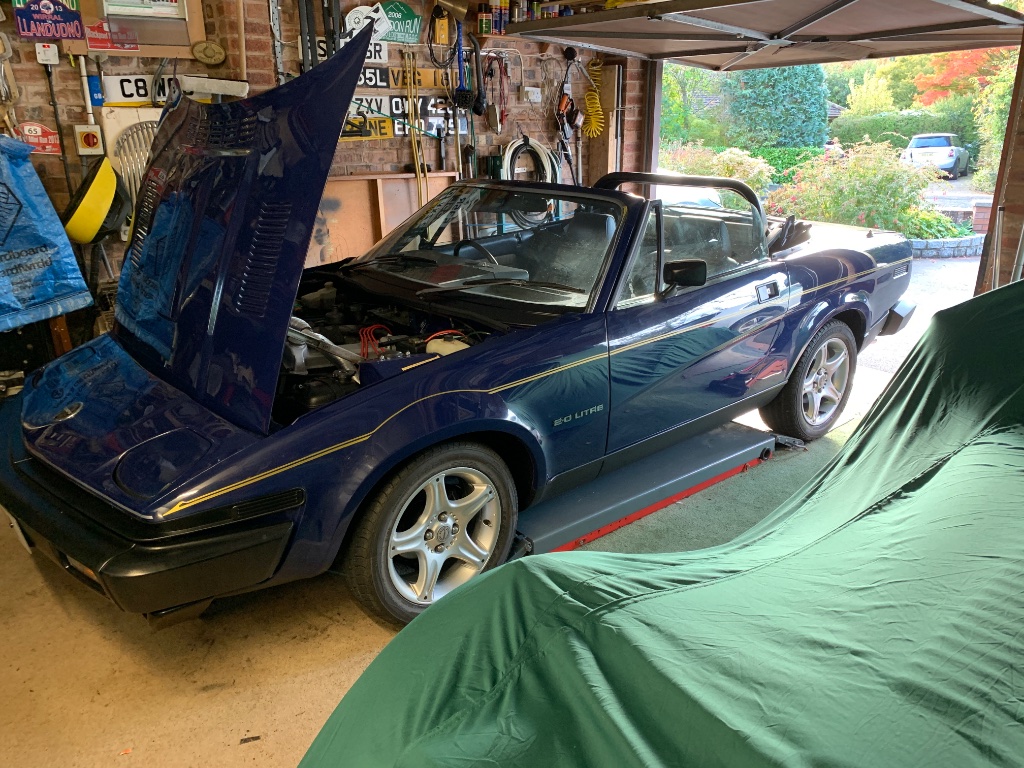
went from this

to this
and balanced the throttle rods on the TR6
busy weekend
-
Hoping to get some time on the car this weekend and looking at fiddling with the throttle linkages etc
I've an inlet airflow meter, more tools than halfords and a reasonable idea how to use them
This is my thinking
With the idle set to 1200 rpm adjust the throttle linkages to give the same airflow through each inlet pair. This may be more reliable across the Rev range if I fit the double ended ball jointed throttle linkages
Simples?
Or have I no idea what I'm talking about?
Thanks, gary.
-
no worries at all, the information about lifters is also relevant as Im hoping to install one apart of the refit, although I'm looking to mount in on the floor not set in (partly due to our intention to move homes in the next 5 years or so). I'm looking at the Automotech one as I had a spider lift years ago when I did my MGB which was fantastic but in the way once the job was finished.
my garage currently looks like this.....

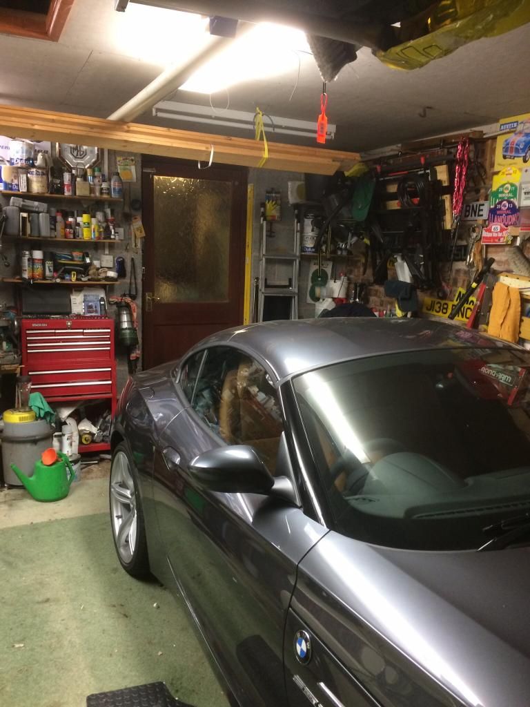
and although magic happens inside I feel need to spruce things up a little
I'm going for
white painted walls
wicks kitchen units in grey with black tops, 3 floor units and 3 wall units
change my large old meddings pillar drill for a more lightweight model
gray tiles on the floor
low level open shelving to the last and right
racking and storage in the loft
car lift on the left where the mini/tr6 lives
my budget is approx £2500
trouble is the floor currently takes up £1000 and I need to reduce this to about £500 then everything works
Gary
-
I used them in my MG days. We invested in a three sets and were very disappointed in the results. Reception variable, volume poor and clarity in an open top car on the move was appalling. More of a risk than an asset. After two summers we sold the lot for about 1/4 of what we paid.
Never again, I use some good quality digital walki talkies in the mini club with much better results, but the minis aren't open top and volume isn't an issue.
-
No idea to be honest
Must be better than the old carpet, paint, cellulose thinners, methanol, white spirit, aerosols, pertol, paraffin, butane and God knows what else is in my garage already. I do have two fire extinguishers though.
-
I'm looking at a garage makeover in the spring and getting everything priced up ready to go
I fancy a vinyl tiled plastic floor in grey but prices seem to be very high. I'm looking at approx 5.2 x 5.3m, giving 30m2 and this seems to be costing over £1000 which is about twice what I was expecting to pay
has anyone any experience with this type of flooring, advice to offer and recommended suppliers
thanks
Gary
-
Here's my understanding of what is legally correct and what is currently standard practice
If your friend uses parts from 2 cars to make one new car the the new car should be re-registered on a Q plate, the remaining parts can be sold individually or as a lot and again registered on a Q plate.
However
The classic car world is littered with cars mixed and matched from two or more other cars with v5 documents and VIN plates fitted to suit. It would be typical of such practice for your friend to make one good car from the best bits of both and use whichever identity he chooses. It would also not be unusual for him then to pass on the remaining parts and identity for another enthusiast to complete a second restoration.
I'm not condoning the above practice as it is bending the law at best but it does allow many classics, particularly the rarer ones, to continue to be on the road.
Gary
-
-
whilst on the subject I cannot recommend the 1.25 ali racing jacks. I have one and compared to my cheaper 3 ton steel jack its very hard work to use. both mine a from machine mart, the ali one was about £100 and the steel one £90. The steel one also lifts more quickly and higher
-
I cant tell from the physical object, both holes look worn, both look well drilled and both look clean
I think from looking at pictures and the geometry of the 'ear' where the hole is located that the outer hole was original. The outer hole is at the centre of the radius of the curve at the bottom of the 'ear'. Why would triumph have located the original hole in a random position relative to the shape of the 'ear'?
That's my reasoning anyway
Gary
-
The hole further from the pivot point will increase the cable travel and also the pull required to apply the brake due to the decrease in angular travel of the lever and reduced lever advantage . Conversely hole near to pivot will reduce cable travel for the same lever angle change thus effort to apply brake will be reduced due to the increased lever advantage ,if there is wear in the system,the hole near to pivot will result in a much longer lever pull. This setting will seem to require less effort to apply a firm brake, pulling through a longer ark you will have in fact used the same energy, levers are great. GIVE ME A LEVER LONG ENOUGH AND A PLACE TO REST IT I WILL MOVE THE WORLD.
Principle of moments. FxS (ccw) =FxS (cw). ( pity apple with its multi billion bollar profit can't let me do simple physics equations easily on my iPad)
Ta
-
Happy hour in the garage tonight and problem solved. With the help of above suggestions, pictures and links I decided to remove the dodgy exterior link straighten it and reshape it to go over and round the pawl. Some careful measurement and marking out and the handbrake now operates as it should. I decided to use the middle hole, nearer the fulcrum and I now have about 50% more travel on the handbrake lever. This should equate to about 30% more force applied to the handbrake linkage at the drum. Some adjustment and I may well be done
Many thanks gents
Gary
-
Interesting Dave. My aim was to keep the jack and axle stand locations as close to the suspension mounts as possible. My thinking is that this replicates the loading when the car is on its wheels. Certainly when I had the car in the air over Xmas to change the exhaust and strip out the radio, opening the doors to get the seats out to sort out the wiring was no problem.
Gary
-
don't know if this is right or wrong but this is how I jacked by car up off all 4 wheels (i have two trolley jacks)
from the front put one jack under each chassis rail where the front wishbone is located
raise the jacks steadily and equally until the front wheels are about 3 inches of the ground
put sturdy axle stands under the chassis and lower the jacks
move to the rear and again use the two trolley jacks roughly level with the rear wheels until the tyres are about 8 inches above the ground
put axle stands under the chassis just ahead of the jacks and carefully lower
move back to the front and repeat the lifting until the wheels are the same height are the rear
adjust the front axle stands to suit
harder to explain the carry out
gary
-
no I think that's how its been modified to a fly off handbrake and the hole drilled.
I think the rod should pass through/over/round the upper part of the pawl but I'm not sure and don't see how it would be attached inside the lever casing
-
thanks, I think you told me about the extra hole on a different thread, I'd like to return the handbrake back to standard but don't know if the parts I have can be used or not. I'm sure the handbrake lever, ratchet and cable attachment are all standard but I'm not sure about the pawl and connecting lever. If they are standard how have they been altered and what should they be returned to?
thanks
Gary
-
I've been looking but can't find one on ebay
I think the connection hooked through the bottom of the pawl should somehow connect to the top of the pawl, but I don't know how
-

this is my handbrake, its got a flyoff mechanism which i don't like. Its also got a second hole to increase the leverage which currently isn't being used.
is this a standard handbrake?, has it been modified and how should it look?
closer pic

I can't figure out how to return the mechanism back to standard so any help would be appreciated
thanks
Gary
-
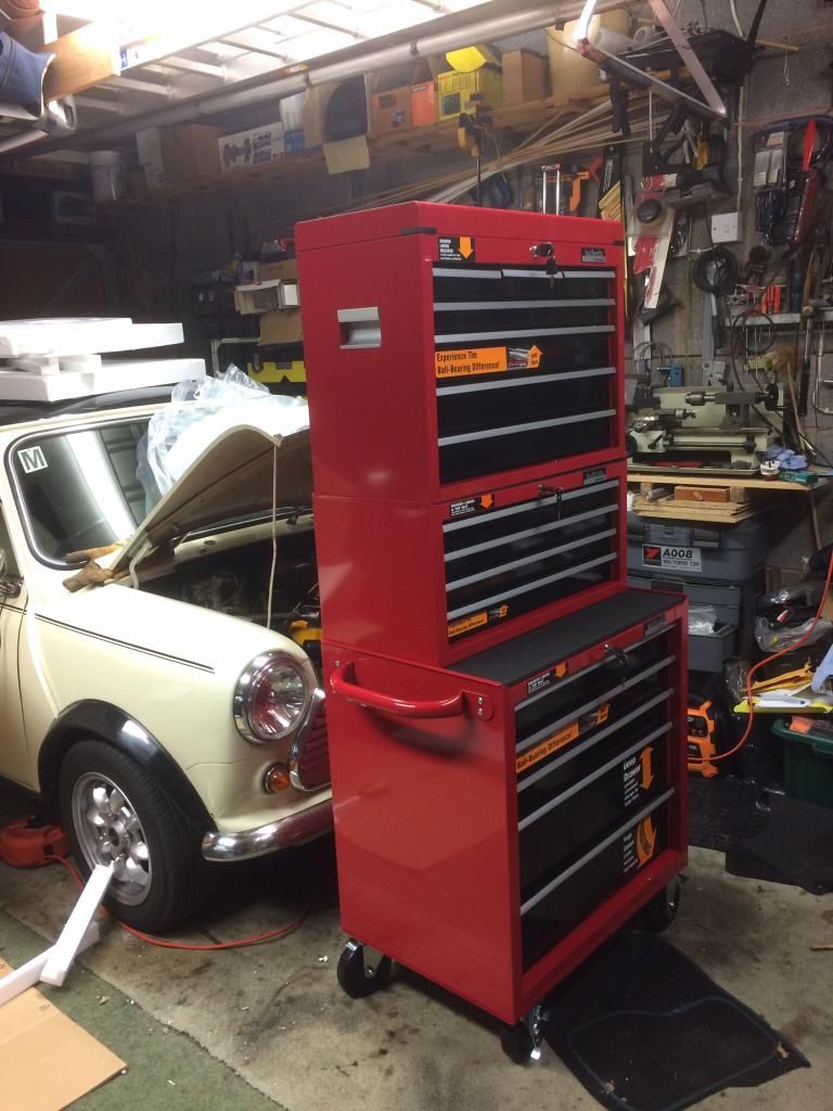
no step ladders but being on the short side I can't see into the top tray!
all done today - ended up splitting the middle section elsewhere
hoping for a full garage makeover laster in the year
-
Finding space for this
-
Forgive me for being daft but how does the 123 system without an injection metering take off point work in a PI car?
Gary
-
Bit like this.
Got it, great.
Re fulcrum increasing force thing. It's the old turning moments thing, tm = force x distance from fulcrum. So if TM is constant then reducing the distance increases the force. Think about using you pliers to cut through wire rod, the closer the rod is the the fulcrum the more force can be applied. The down side is the other side of the fulcrum has to move further to compensate.


garage flooring
in General TR Technical
Posted
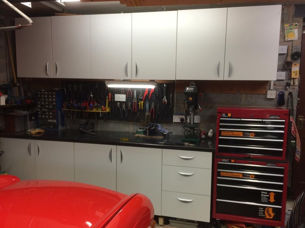
this is how it looks now
that little space has all been used up!
still not sorted the flooring situation, but I could go down the route of carpet - its what i have at the moment.
I'm also looking for a nice metal A3 sized TR6 wall plaque to go with the MINI, MGB and Stag ones I currently have