


oldtuckunder
-
Content Count
1,240 -
Joined
-
Last visited
Content Type
Profiles
Forums
Calendar
Posts posted by oldtuckunder
-
-
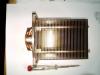
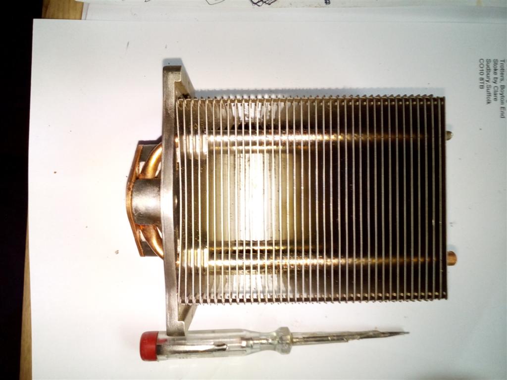
Alan - please note that I have found some data on the heat sinks of a similar-sized unit which states that additional heat sinking or fan cooling will be required if the modules are run at max output.
I noticed on the board that there are two connection points marked +/- with the legend "fan" etched on the board. I have a cupboard full of little PC cooling fans so may see about incorporating one.
Of course I do have a nice freon filled heat sink, but hopefully that would be overkill

Alan
-
I think Alan is probably intending to use standard 12v to 5v converters from his 'clean' 12volt supply. Not really necessary of course as he could set the output of the dc-dc converter to 5v
Yes I already run some devices of a 12v to 5v converter, so my plan was get a clean 12v supply for the bits that need 12v and take a feed to the 12-5 converter from that as well, should be able to make a neat supply block and reduce the spaghetti a bit. I have always tried with the wiring to leave the standard loom intact in case at some point someone wanted to revert to plain vanilla.
-
Hi Roger
Well I'm still running on a dynamo working on if it ain't broke don't fix it, (and I very rarely use lights) which I know can be spikier than alternators. However one of the reasons for a clean 12v supply is the Innovate kit, which on some of the logs is showing symptoms of spiky voltage, hanging the MJ off it is just extra caution.
When I said wow earlier in thread about quick answer to question, I have a double wow today, ordered item yesterday afternoon (Sunday) on eBay arrived by courier 11 am. this morning! £10.50 with Free Delivery! These Chinese are getting dam slick, or can they read minds? or have the Chinese government hacked the TR Register Forum?
Alan
-
How hot will it get?
I suspect just for MJ
 hardly at all, but I also want to drive the Innovate Datalogger that in turn supplies two wideband sensors which may well take 6-8 amps peak load. Also realised that I can use this as a clean supply for the little 12-5v converter I use to power TPS and MAP sensor.
Ah but you have made me think that I must go back and look at MJ wiring and decide if I need/want/have to feed EDIS or Coil Pack from same supply as the MJ, or if they only need to share common earth.
Alan
-
You will be tuning your vitesse between runs with a laptop if you carry on like this ?!?!?
Hoping for simple Street/Strip dash switch
Wow Guys, less than an hour to solution!
Yes thats right but if you are going to draw 10 amps use a bigger fuse to allow for the unit efficiency and to give a bit of margin. 15A should be fine.
You DO have to get it right but if you do the diode is not necessary.
The unit is quite efficient - they say 'up to 95%' but assume in the region of 80% at worst - so at full whack the heatsink may be dissipating up to 20 Watts. Enough to get hot in still air so it needs reasonable ventilation. When you enclose it, you need to ensure maximum air-flow so some sort of wire mesh or expanded metal cover would be good. It shouldn't be necessary to use a bigger heatsink but there's nothing to stop you doing that. Just check first that the heatsinks are not 'live'. ( They shouidn't be but you never know....)
Thank's Rob that amount of solid input has probably paid for my TR Membership this year! I'd buy you a Pint but they have shut the Bar!

Alan
-
Wow Guys, less than an hour to solution!
So excusing my electrical ignorance, it looks like the device that Peter posted, I hook up to to the cars 12v supply via a switched relay, and probably an inline 10 amp fuse, take the output supply (and presumably twiddle the little screw on the blue adjuster to set the output to 12v?)
Couple of quick questions it says
Overtemperature protection: Yes (overtemperature automatically switches off the output)
Input polarity protection: None (please install diode at input connector)
I'm assuming I don't have to worry about polarity protection if I get my +/- correct?
As its rated for 12 amps and the max I think I will ever draw is 10 amps and not continuous, do I have to worry about overtemp? only asking as I don't want a dead car on a hot day? Ensure I mount somewhere with air flow, think about a bigger heat sink?
Alan
-
Hi Folks
Anyone got any ideas how to create a clean 12v supply on a car.
I now have several electronic devices on the car that really need a clean 12V supply, and I know that Dynamos and Voltage Regulators and Alternator supplies are variable at best and spikey at worst. I also discovered a month or two back that even things like simple timing strobes that plug into HT leads (rather than use an inductive clamp) can actually send very high voltage spikes back down their power supply cable to the battery.
So I'd like to create a clean 12v supply point, that I can enable when turning on ignition, but that is isolated from the voltage the battery sees, but ideally shares a common negative earth of the chassis/bodyshell.
So what I think I want is a small 12v to 12v transformer that I can switch on via a relay, and reconnect the negative of the output back to chassis ground. No large current requirements, think absolute max I require is 10 amps.
Would this work? any brighter ideas?
Alan
-
-
For instance 3000 revs in overdrive was just under 90 mph, but with the mew electronic setup its just over 80
I was surprised, as i though the tacho would likely overrread not under.
I’m about to rebuild the tacho and conver to electronic, will be interesting to see if the two electronic tachos agree!
Given there is no direct connection between the spinning head and the needle, 40+ years of gunk on the needle spindle etc could well retard the mechanical needle swing. In my experience the mechanical Tacho's all over read a bit, just to match the over reading Speedo's.
As regarding the two electronic tachos agreeing, they probably will as some point, but not everywhere. The pure electronic one you have will (should have) a sweep hand mechanism calibrated to the dial (unless its digital in which case unless proved incorrect assume correct). The conversion probably won't, they are sort of there/thereabouts but you will normally find that they either read about right down at the idle end (which apparently most people prefer) but are out at the high end, or vice versa.
Personally with a conversion I don't worry about how accurate it is at idle, makes very little difference if its a few hundred rpm out, but I do want it accurate at the top end where under reading by 500+ rpm can mean straying into danger territory without knowing. The professional electronic conversion of my Vitesse one is unfortunately neither fish nor fowl, it over reads at idle (which I don't mind) but despite me requesting top end accurate rather than bottom, it actually under reads at the top end, I suspect probably because I didn't specify that top end meant 6.5 - 7K not around the 5.5K mark. Didn't discover this until fitting the data logger and discovered that I was regularly exceeding my desired max rpm by around 350 rpm.
Alan
-
I think the rule is if you have a mild steel exhaust headers and wrap it, it will promote corrosion deterioration, which can be fairly quick. If you have Stainless Steel exhaust headers they are fine wrapped.
Wrap does work though!
From my experience the further you get away from the header pipes the less the corrosion problem is with mild steel, so primary pipes and first collectors suffer badly, next 12" of pipe suffer a bit, after that virtually no signs of corrosion. So by the time you get to the sections under the starter motor just wrapping those even if mild steel shouldn't be a problem. Of course at that point its easier to just wrap the starter motor!
Alan
-
Slightly surprised under the new rules that this thread has survived so long being non car related, if the
moderatorsmoderator was doing the job properly this would long have been moved to the "Ungrateful Bastar.s don't appreciate what we are doing for them" Forum
-
so I coated my TR exhaust manifold with metal sprayed aluminium (one Friday afternoon, as you do) and now after some 45 years, it is only just starting to flake. I had a big box for my lunch that day!
My own TR has wrapped stainless steel exhaust manifold now and I am pleased with the underbonnet temp drop and the improved 'stuck in traffic' tickover.
Funny! I have the original Cast manifold for my Vitesse still in storage. An Uncle must have borrowed your Lunch box as he got it Aluminium sprayed for me at Rolls Royce engines in Bristol back in the late 70's. Sat around for decades it still only has the slightest traces of surface rust, mainly around the bolt holes where I think a bit of stress cracking of aluminium must occur.
I'm fairly certain that after coating that I will find that I still need to wrap the headers, but we will see?
Alan
-
Just noticed that the Bar has closed also, and that I shouldn't have even started this thread here, so blink and you'll miss it

"instruct the moderators to remove all other non-technical conversations from outside of the Members Chat area - with immediate effect."
-
Or have I just had a senior moment?
Alan
-
There is indeed high wear when the engine in is being started, whether oil is hot or cold. The rpm are so low that ther'es no dynamic lubircation, no wedge of high pressure oil separating crank from shells.
I have found a pre-oiler helps with this, or at least makes it less painful emotionally when starting the engine to see the oil pressure around 50psi before you push the button

I'm fairly certain Marcus had a thread on here a year or so back on implementing one on his GT6, I just slavishly ripped off his design with a few mods to suit my application.
Alan
Alan
-
We have this on the aircraft but use the fuel rather than water - Fuel cooled oil cooler.
Ah a bit on the lines of the XJS that had an aircon/fuel heat exchanger to take the heat out of the injection return fuel line to the tank. Always thought that was a clever idea to keep the fuel tank cool.
-
Interesting thread.
Biggest lesson I have learn't over last two years in (hopefully) solving my #5 BE problem, is fit an oil temp gauge! as others have said its lack of flow (either continuous or momentary "probably too quick to register") not pressure that will kill an engine.
With an oil temp gauge you will quickly learn that (in the UK) oil takes a long time to warm up, that you are abusing the engine when the oil is too cold, and a lot of the time the oil is only occasionally reaching its designed working temp. Unless your racing and know the oil is up to temp, if you have an oil cooler fitted without a thermostat most of the time you are just robbing the engine of power and necessary lubrication, If you have an oil stat fitted and it opens any less than 85C then you are doing the same! In the UK a lot of the time you want to be putting heat into the oil not taking it out! Why do you think so many moderns designed to run on lower viscosity fully synthetic oils now fit oil/water heat exchangers and don't bother with oil coolers. A heat exchanger will warm the oil up quicker (when all the damage is being done) and will cool it when the oil temp starts rising above coolant temp.
Even a 0w oil is too thick to lubricate an engine properly at 75F, so on a warm summers day when you first start your classic filled with Classic Mineral 20w50 just take it real easy for a bit! Oh and its cools down quick in the sump also, I can finish a run with the oil approaching 100C let it stand for an hour or so and it will be back down below 50C and too low to push the engine hard.
If you have an oil temp gauge plus an oil pressure gauge you can watch exactly the correlation between the two, there is very little correlation between coolant temp, oil temp, and oil pressure (unless you have a heat exchanger) If you have all three gauges you will have a ery good view of what is happening in your engine. If I had to junk two of the gauges it would be pressure and coolant temp, if you only have an oil temp gauge and a pressure idiot light you will have a better information than the other two put together.
Guess I'll get flamed for this!
Alan
-
Alan, could you please tell me why it needed 4 builds in 4 years ?
He is a highly competitive and successful racer.
And these finely tuned and heavily thrashed motors need winter TLC
And he likes to tinker ........
Whilst the latter is probably true, I'd like to think the former was, but unfortunately the truth is that the first three rebuilds were down to catastrophic failure of #5 Big End
There is a long thread on my travails in solving this
http://www.tr-register.co.uk/forums/index.php?/topic/50972-new-crank-required-streached-big-end-cap/
The forth rebuild end 2016 was just to have a look as the engine had survived 2016, and I wondered if it had really survived or was on the point of giving up, it was good!
I will admit that the current head off exercise is closer to the tinkering exercise, but includes a few tweaks for next season!
Alan
-
I may be anal (but having carefully timed a cam off #1 Valve, rather than #1 Inlet Valve in the past) I don't trust any timing marks unless I have made them, and even then have my doubts!
So I always time the cam from scratch, and use any marks I previously made as a visual check that I probably have it right, or that I should double check, which as you can see from my first sentence I now tend to do anyway!
Alan
NB an adjustable top sprocket does make it all a lot easier!
-
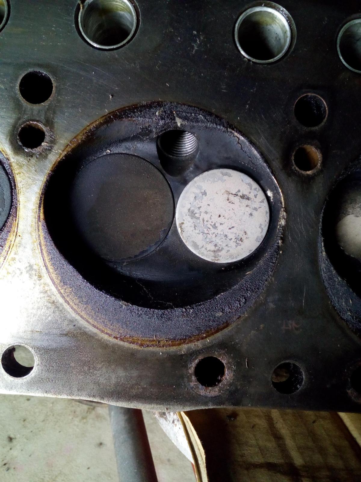
Alan, that inlet valve looks to be far to deep in the heed
valve seat been re cut too many times
or inlet re cut !!
there some pile of sheite inthem chambers for just a seasons blasting up a hill,
or are ye running it ont road as weel,!!
Best way t,clean yer cyl chambers oot, is t,bung water in inlet mani
the water turns t,steam, an blast the deposits away
an water costs nowt,!!!
Yes not much metal left, standard steel valves sit a bit higher, but the rim flow stainless sit low, still manage to get a neat thin seal when lapping in, but if it goes bad its metal spraying time, as there is not enough metal to even attempt inserts (which I don't like anyway). The MK1 head isn't supposed to be able to take the 36.5mm Inlets so its a bit of a miracle anyway!
Yes it did some road mileage last season, as I did a number of events in the road going class, so driving to/from is mandated. Next season back to modified as the rule changes mean I'm excluded in more ways than one from road going.
Might try the water injection clean up during next season!
Am hoping Alan will analyse the white powder and tackle BP...
Well I'm happy to scrape some off, if someone can tell me what to do with it!
Alan
-
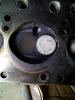
What grease? and how liberal?
I have used both LM and Moly grease, usually LM as it saves having black smears around. If you look a the second picture you can see a small pool of LM left in the depression that blanks off the water way.
I usually coat the the top of the block, then drop the gasket on, then coat the top of the gasket, then drop the head on, as it makes it easier smearing grease on a firm surface, and also saves handling the gasket too much when unsupported.
How thick? Well sort of even coating as it goes on with a finger tip, I'd guess I use about 1cu inch per face.
NB if I'm using a new gasket, I'll check torque within an hour of first start up, and then again after another few hours or a couple of hundred mile. My theory is that most of the expansion/contraction occurs within the first few full heat cycles, and I'd rather make sure it was torqued properly sooner rather than later and risk it.
Second time onwards, I'll just check after a couple of hours of running, but to be honest its more a belt and braces check, as it never seems to move.
NB on a MK1 head this is more of an advantage than the MK2 as with the MK1 I have to unbolt the headers and inlet manifold to get at the outer row of bolts!
Alan
-
Just thought I'd post a picture of a Payen Head Gasket after its fourth rebuild use!
My father taught me to clean all the sticky gunk off new Payen Gaskets, and fit with liberal amounts of grease on both sides, partly because of cost, but mainly because it meant it was quick and easy to remove and refit head. Some 45+ years on and I still continue to do so, and touch wood have never had any head gasket problems. One of the major advantages I have found with reuse is that after first fit and re torque the gasket has just about done all its compression, and on subsequent rebuilds a re torque is not normally needed, also on rebuild if I haven't played with rocker shaft assembly the tappet setting are still almost perfect, although I always check and reset.
Of course it only works if you don't play with either the head or block surfaces other than perfectly cleaning them between builds, as the copper has just about perfectly formed to both surfaces.
This one after 4 builds in 4 years has actually reached the end of its life, its showing a tiny burn mark on the edge of the copper in #4 next to the narrow land to #3, and whilst if it had been left undisturbed I'm sure would have lasted a long time, its not worth the risk. I don't do it purely for cost, Payen's for my MK1 head are scarce so I'm trying to eke out my small stock.
No doubt others will think it a complete an utter waste of time and risky.
Alan
-
Hi
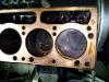
No fuel additives used, apart from what they bung in at manufacture, which just out of interest since rebuild in march this engine has only been run on BP Ultimate and not a drop of anything else.
Finally got head off (world kept interrupting me) and below is a chamber shot, which seems to be just about exactly as expected.
Alan
-
My point is that it was a cold car to drive. Almost all the heat under the bonnet comes from the radiator. Even with a tubular manifold (more surface area, so more heat loss than a cast) it never got hot there, The pipes were hot, but nothing else.
Reinforces my comment earlier in the thread that the temp of the pipes dropped almost instantly the fan cuts in, even if that air is warmed by the Rad its way cooler than the wrapped pipe. So may be although I have extensive heat shielding keeping the carbs and inlet cool and separated from the rest of the under bonnet area, it may be a good ideas to investigate managing the air flow when the fan cuts in (especially when idling as that is when the temps really start rising) to direct it away from the header pipes so they stop acting like a fan heater.
Alan


Clean 12V supply
in General TR Technical
Posted
I guess the easy way to find out is when I hook it up to a charged car battery and bung a meter on the output and measure it. Guess when engine is back running I can do the same with engine at tickover (not that my tickover is ever less than around 950/1k) I assume best way to measure would be with a small load like a light bulb running off the output rather than unloaded or doesn't it matter?