

mleadbeater
-
Content Count
323 -
Joined
-
Last visited
Content Type
Profiles
Forums
Calendar
Posts posted by mleadbeater
-
-
Hi,
I’m thinking of replacing the wind up windows on my ‘6 as they are badly scuffed by the hood frame rubbers, and not too dear to buy new.
My question is: is there any easy way to remove and replace the glass, or am I condemned to removing a lot of periferal gubbins to do this. Can the glass be prised out of the bottom holder in place?
One of my most disliked jobs is working on these fiddly doors.
Is there a good “ how to “ guide on t’net?
Cheers
Mike
-
Cheers, Stuart, that’s only about 60 miles away.
-
hi,
no, i’m near York, thanks , long trip to London, especially in a 50 year old, the car not me!
I’ll keep pondering and tweaking for now, its only a toy.
cheers
Mike
-
John,
looks like he is not around anymore, looking at the website.
I may have to resort to finding a specialist, but I’ll keep learning and trying for a while longer.
cheers
Mike
-
David,
Yes, but which screw do I adjust?, large one already fully in.
Mike
-
Hi,
thanks for the further advice.
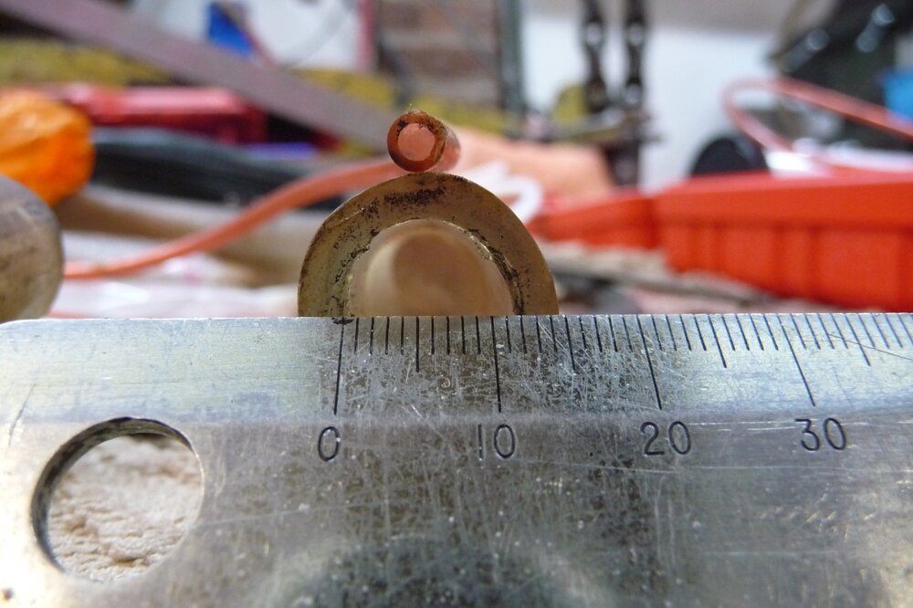
just done some experiments on the PI, trying different diameters of vacuum hose connecting it to the centre pair of inlet manifolds.
I tried a small bore hose, 2.3 mm internal dia, and then a larger diameter of 12 mm, not a lot of difference but the larger hose seemed a little better, with less bogging. I guess its a balance between flow resistance of a small hose versus the reservoir capacity of a larger one.
Probably the best solution is a short as possible hose with a say 12 mm bore. More testing is possible in the spring when the car is back on the road.
re adjusting the fueling screws, the large on seems fully screwed in, so which other one should I try next?
cheers
Mike
-
Thanks, gents, for your responses, the mysteries of the MU are a getting clearer.
Peter, you link is very helpful, clarifying my understanding of the PI system, which lacks any enrichment device , running rich seems a poor compromise these days.
Martin, thanks for your kind offer, I am in York, so a bit far from you, essentially in a ‘6 not running right. I may ask you for some help on your “ analysing setup”, if thsts ok, but it won’t be until spring. The car is currently tucked away in my garage, undergoing many tidy-up jobs.
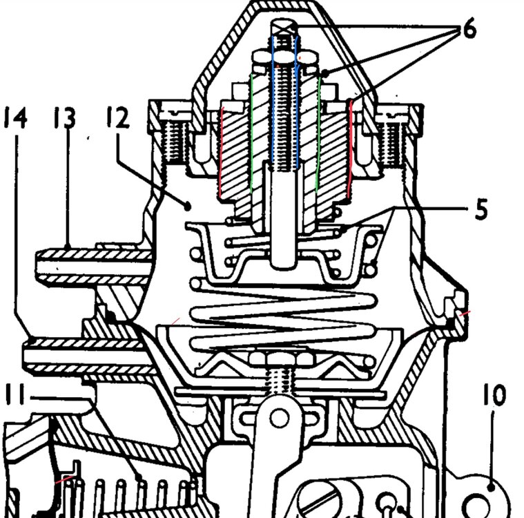
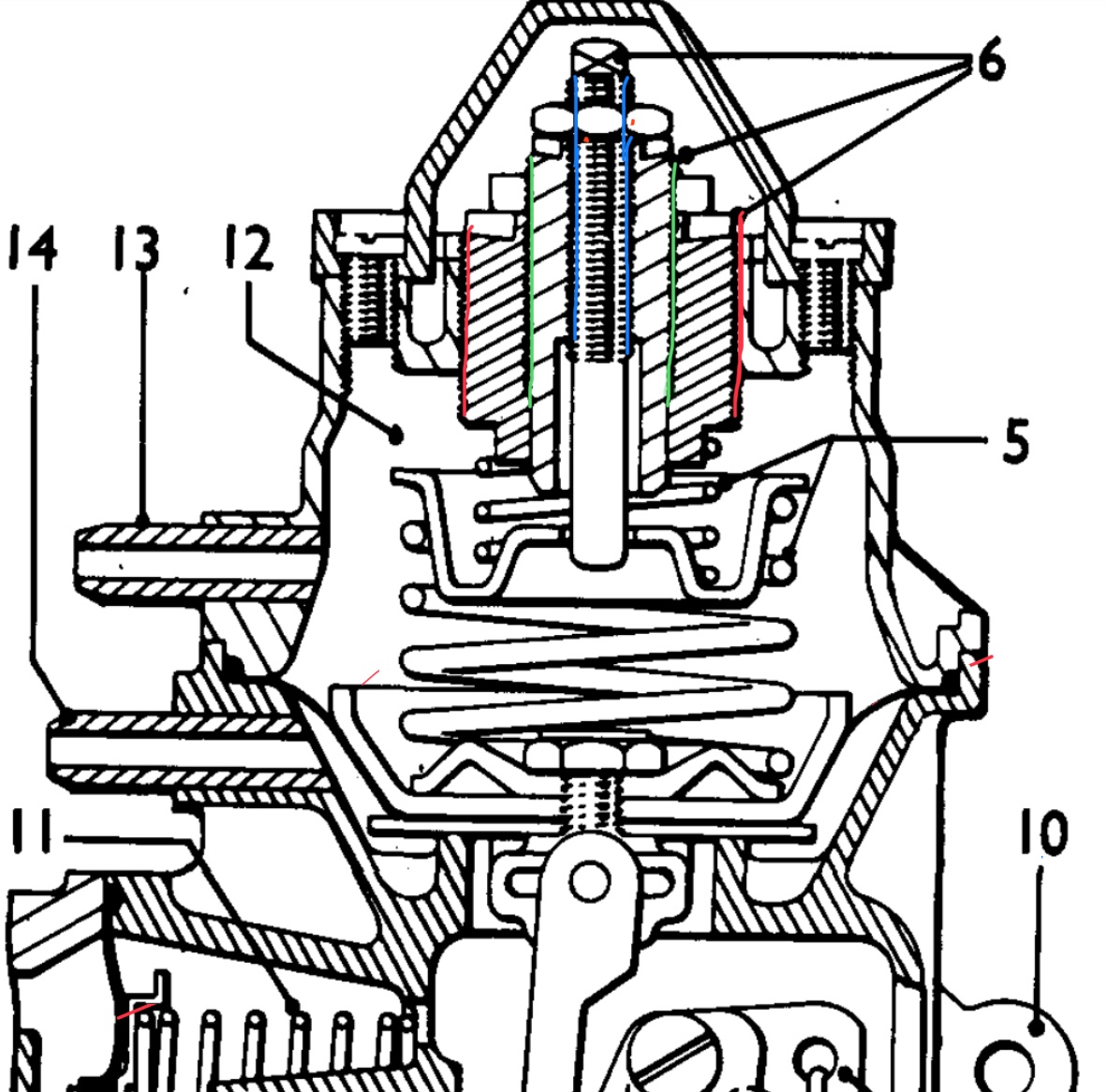
John, your comments are most helpful in demystifying the workings of the diaphragm and spring system, I attach a cross section , the three threaded adjustments are coloured, can you tell me the individual functions of each?, also the individual function of the two springs.
You mention fitting a top gasket, is this to make it airtight to maintain the vacuum?
My car is a mid 70’s CR, the plugs looked the correct light brown last time I checked, I also checked with my colortune, the flame was a correct blue at idle.
Are there anymore writeups on t’net on the operation of the MU? , I hate manuals which state never mess with these units, words like Rag, Red, and Bull come to mind.
Thanks again
Mike
-
take your point, Mike, but, having tried adjusting the butterflies as well as possible, checked compressions, fuel pressure, vacuum, and installed a new distributor with electrictronic ignition, the engine still bogs. My thoughts are all about minimising vacuum release lag to the MU when the vacuum at the manifold rapidly drops on acceleration.
Otherwise the tickover is stable and can be adjusted between approximately 600 to 1200 rpm, starting easy with the enrichement lever, and it revs freely to high rpm cleanly once past the bog rpm.
I will check the injectors as well, but otherwise its still bogging.
Testing my theory won’t cost me anything, and is easily reversible, so worth a try.
Ultimately, I may need to have the MU rebuild and recalibrated.
All part of the fun of ownership,
Mike
-
Peter,
I was just thinking of using rubber hoses, nylon tubing , of which I have a selection, and jubilee clips, leaks shouldn’t be a problem if I take care, but thanks for your concern.
Mike
-
As per my recent posts on the performance on my car’s PI system, which is performing reasonably well, but still has a bogging issue on snap throttle opening, I have been pondering, .. a common activity for me, especially on cold winter evenings.
One thing I wondered was the influence of the size of the vacuum hose from the manifold to metering unit.
My reasoning , based on a “thought experiment “, is that a very large pipe would act as a vacuum reservoir, and would slug the unit’s response, and , on the other extreme, a small bore pipe would give a more rapid response , possibly helping to reduce the bogging issue.
Before I raid my “hose box” and start trying different sizes, has anyone any experience of this issue?
Cheers
Mike
-
George,
like your idea, I was thinking of replacing the intact but battered millboard boot lining with the same, but its so susceptible to damage that it would soon be scrubbed again.
This lining material is cheap and easy to cut I guess, will definitely get some, ebay I guess.
nb make sure you use decent impact adhesive, both high strength and heat resistant, cheaper stuff lets go , as I've found out the hard way.
Mike
-
It goes soft in water, but doesn’t disintergrate, so needs sealing inside, any waterproof paint should do, will dig-in my paint cupboard. I guess water softenning is a good way to form folds without splitting.
Mike
-
Although I haven’t given up trying to sort my ‘6 ‘s PI syste, on which the main issue is the tendency to bog on acceleration , Ive had thoughts about converting to carbs. Can you please comment on the following question.
If converting to carbs, probably SUs or Strombergs, roughly how much power loss will this produce? and change in economy?
What are the pros/cons of these carbs?
Is my car, a mid 73 model fitted with the long port head? how do I tell the difference?
Webers are another option, and comments on these?, are used ones ok?
Finally , any experience with converting to electronic PI?
I don’t want to spend a lot on my car, just want it to be a pleasure to drive, not too worried about driving quickly.
Cheers
Mike
-
Thanks for the feedback, i’m conducting a soak test on an offcut, to determine susceptibility to water.
Cheers
Mike
-
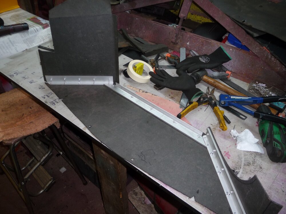
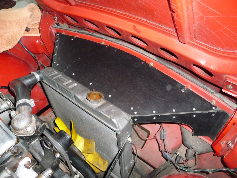
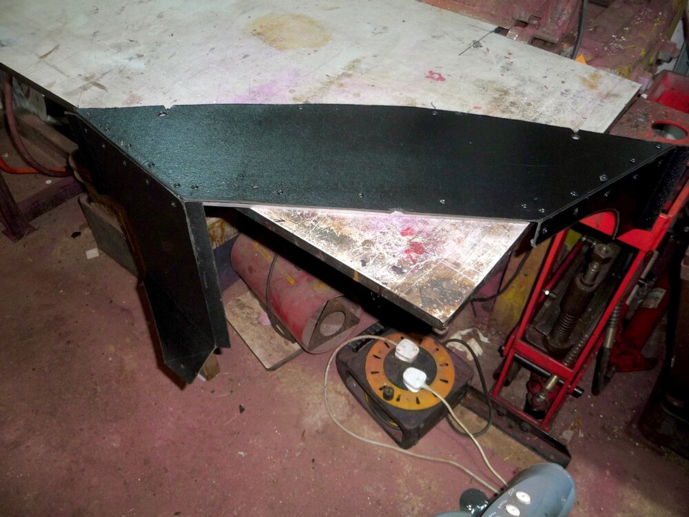
Just finished my DIY version, I had the millboard/fibreboard in stock, and found some ally angle in my shed, plus a few 4 mm blind rivets, total cost: nowt, very happy.
n.b. “nowt” is a Yorkshirism for nothing.
Yet to fit as just tidying the front end wiring, and applying some rust prevention wax to the front valance.
An easy job if you have a pattern.
Cheers
Mike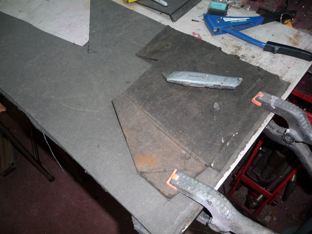
-
Hi
if it is the cutoff (inertia ) switch that is faulty, as mine was, I obtained a modern one from ebay, eg as per link below.
Make sure you get one with a plug and wires included. By cutting off the lugs on the switch body, it can be held in the original clip, retained by a small cable tie around the front lugs of the clip.
https://www.ebay.co.uk/itm/386244850594?
In my view, these modern switches should be more reliable than the original 50 + year old design, they certainly are fitted to millions of moderns, not commonly known as a problematic device.
Cheers
Mike
-
Below is a photo of the remaining half of the 2.5 m I bought from above link, for interest.
Mike
-
Thanks, all, for your positive comments.
Phil, link to veneer supplier,
https://www.ebay.co.uk/usr/perfect_body_center
I still have half the piece left over, sufficient to do another, if this of interest let me know, I doubt I’ll use it myself.
Andy, no intention to do the door cappings , apart from maybe recovering in leather or vinyl , the standard ones are admittedly a bit crappy. Have you made new ones yourself?
Pete, your Daimler dash looks a little more ambitious, I would consider looking at using a vacuum bag for this type of job, it would get over clamping issues, and should flatten the usual rippling if using burr veneers. .n.b. love these old Daimlers, still on my wish list, although a little big to fit in my ever-filling garage.
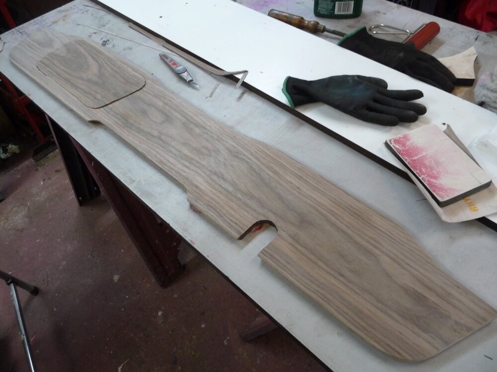
Steve B: re matching the glovebox veneer; by not applying glue to the veneer, and carefully cutting out the remaining box front after gluing the main section , see last photo, I could then glue the box front at leisure . Matching was then a no- brainer. The ply box front was a remade one , which required cutting out the lock “ keyhole “, fortunately I was able to use my milling machine, a must for any car restorer, along with a lathe.
Cheers,
Mike
-
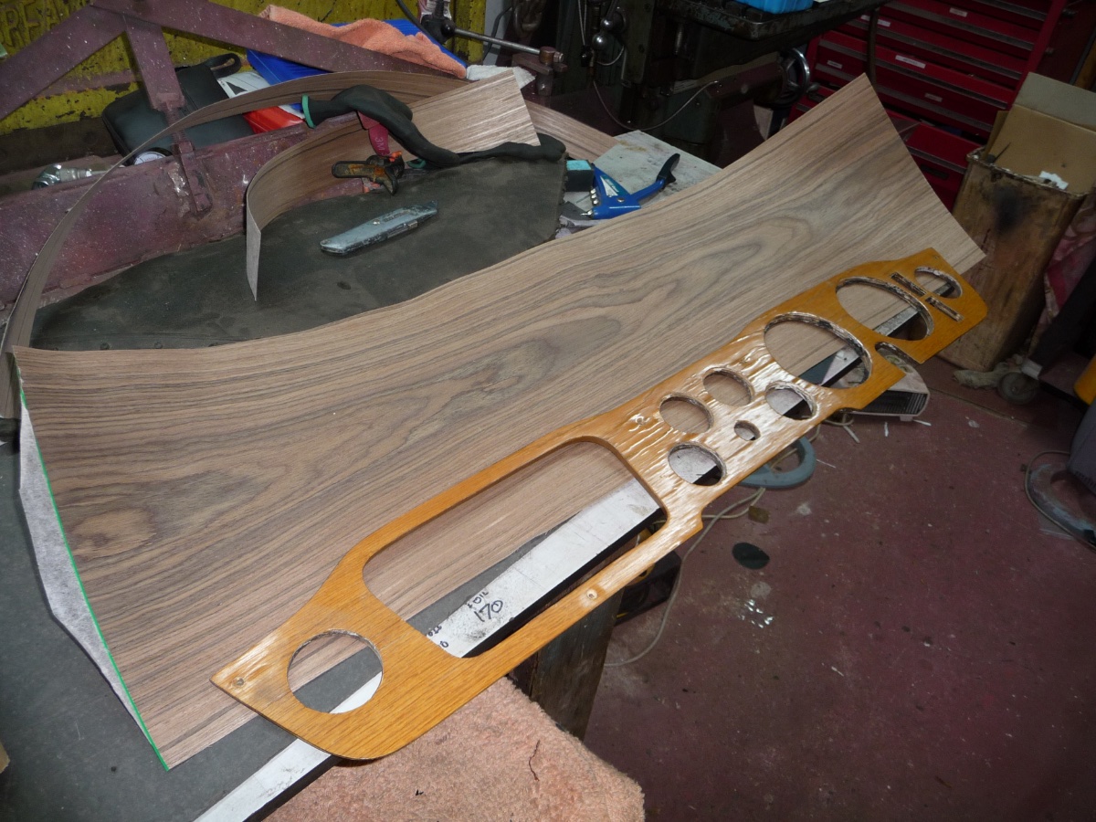
As promised in an earlier post, here’s a brief summary of my efforts to refurbish my ‘6’s tatty dash. Not a full write-up as plenty of info online, just some experiences and suggestions.
My preference for the ‘6 dash is for the semi-matt finish of nicely grained veneer , rather than a high-gloss burr veneered one.
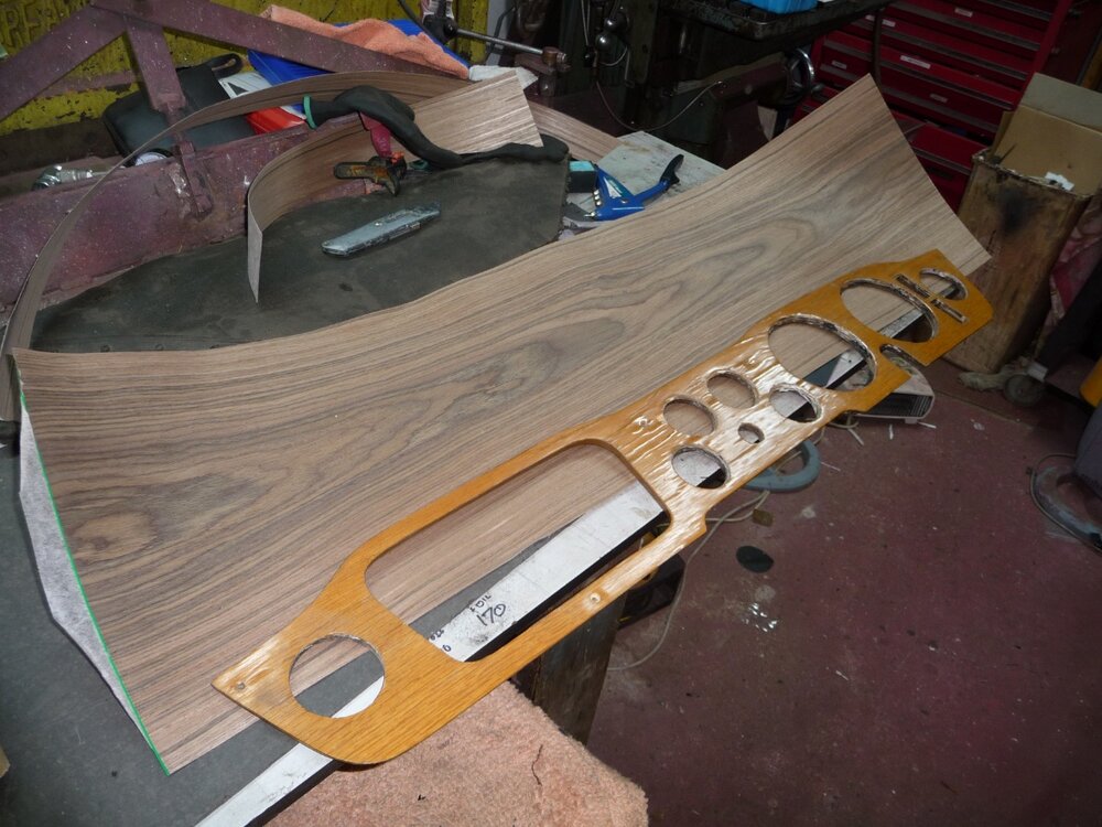
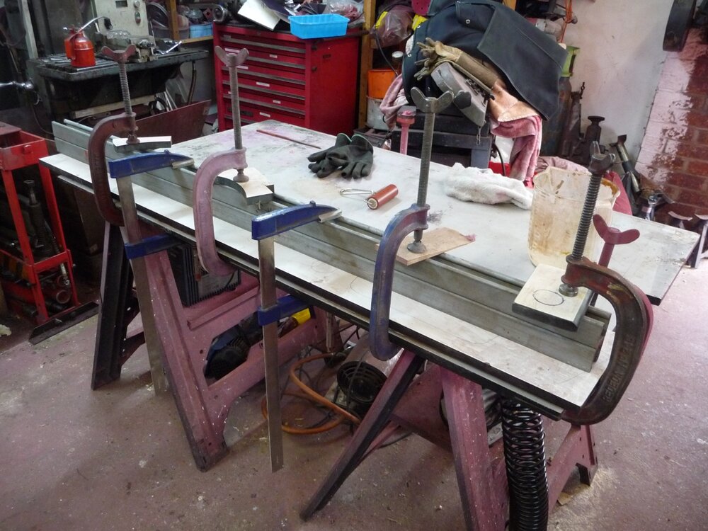
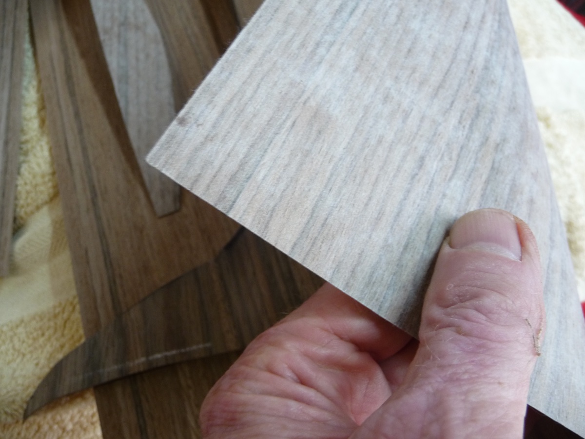
Also, the cost of these high gloss dashes is a big negative , and the pleasure and satisfaction of my diy efforts is the main reason for buying classics which need restoration.I reveneered an old original dash, using American Walnut, at a minimal cost of around £18 for a length sufficient to do two, bought on ebay.
This is paper-backed, and nice and flat without the worry of rippling or splits, and needing only simple clamping between two flat surfaces, using PVA glue, applied to the dash only, spread by roller, (ex photo printing rubber glossing roller) ,see photos below.
The old varnish, original I guess, easily flaked off back to the original veneer, and required minimal filling and flatting, using body filler.
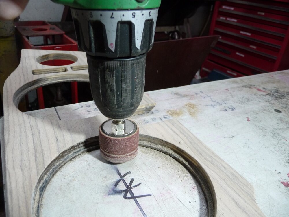
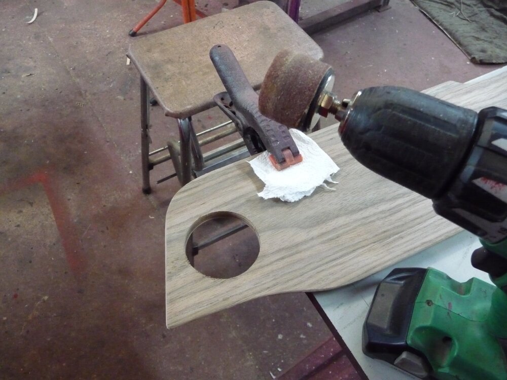
Finishing the internal edges of the instrument holes caused me concern as I wished to avoid chipped veneer, so I used a small emery drum sander in a hand battery drill to remove the excess veneer , after roughly removing the centres with a sharp craft knife, face down. Finish the veneer with 600 grit abrasive paper on a flat rubbing block, being careful at the edges.
Using a resin and oil based finish, Danish oil, I achieved a very acceptable and hopefully durable appearance which I am very happy with, only needing about 5 coats with overnight drying and minimal rubbing down , and a final buff with beeswax.
The oil based finish is considerably less hassle compared to trying to get a perfect full gloss finish, probably taking around 1/4 of the time.
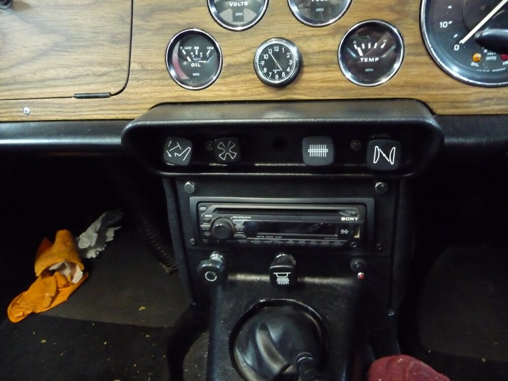
I took the opportunity to modify the switch positions, moving the virtually unused instrument dimmer to lower down the facia, and adding a small push button switch for the screen wash pump, adjacent to the wiper switch. I also added , centrally between the tach and speedo, a red led light for low oil pressure, set via an adjustable oil pressure sensor to around 40psi, and a green led light for the direction indicators as the instrument mounted original is hidden by the steering wheel. A good tip is to make a veneered test piece on some scrap ply, so that you can test-drill holes for these extras to check the size and non tearout of the drill used. I used spade wood drills, well sharpened.
Finally, after much deliberation on alternative switches or instruments in place of the dimmer, I fitted a low cost clock, which has its own internal battery and is simply held on to the dash by double sided tape. Easy to remove if I decide to fit some other device, maybe a vacuum gauge.
n.b. I have blanked off the rheostat hole before veneering.
My advice is, if you have some woodworking skills, to have a go, save a small fortune and have the satisfaction of doing it yourself.
Hope this is of interest, some photos below.
Mike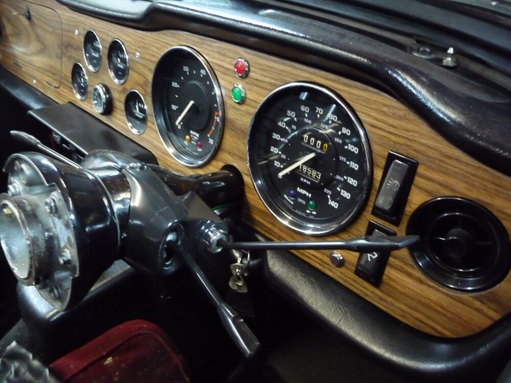

-
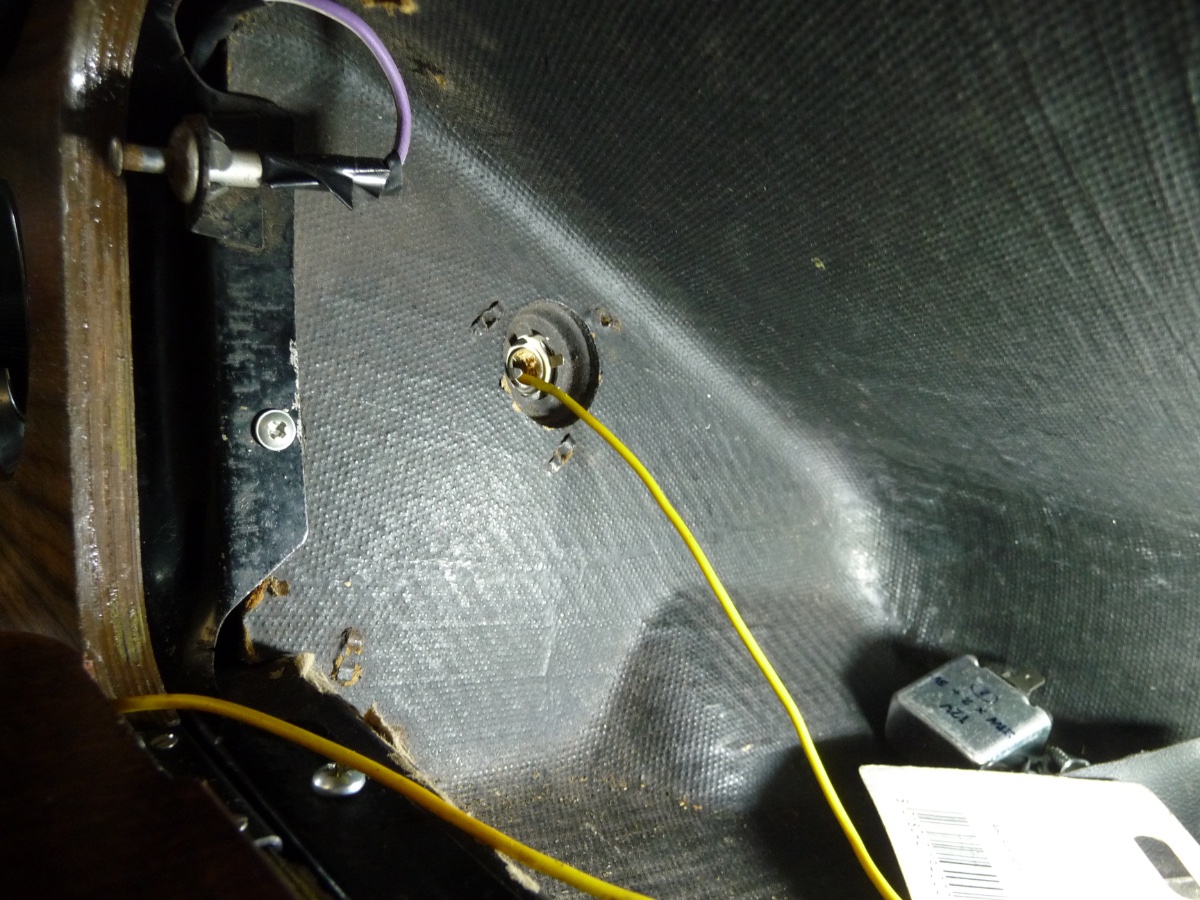
Whilst attempting to remove the glove box I removed the internal bulbholder, and then gave up on removal of the glove box as it seemed a lot of work, deciding to keep it.
My attempts to replace the bulbholder, without removing lots of ductwork, proved virtually impossible.
After some thought I came up with the following solution, which was successful at the first attempt .
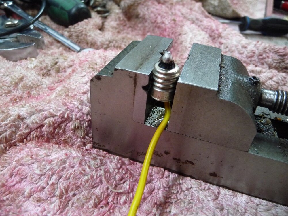
This was to remove the bulb, remove the bulb glass, and replace it with a length of wire, soldered in. Then by feeding the wire down through the holder hole, inserting the bulb base into the holder, and drawing the holder back up and into position…job done.
Hope this helps someone with the same problem.
Cheers
Mike.

-
If running rich I doubt you’d smell petrol, you'd notice black fume’s from the exhaust, and the plugs would be sooty.
A petrol smell is more likely from a leak as suggested.
Mike
-
There are often autojumble stallholders who sell a range of keys and are happy to let you try to find one that works.
Mike
-
Rob,
thanks for the explanation, makes sense.
The clipon ammeter looks a good bet, much safer than using a multi meter on amps settling, which if used across a battery will cause a dead short and fry the meter unless well fused. If using a multimeter, be VERY careful if measuring amps, an ammeter has very low internal resistance and should be used in series with a load, the voltage setting is much safer as its a high resistance device and wont cause a short, only passing a few milliamps.
-
from my experience, if a lead acid battery has been flat for several weeks, it is definitely junk.
re ammeters vs voltmeters, as I’ve said, voltmeters are so cheap you can have both, as I have in my TD. The voltmeter will tell you the battery voltage before starting, then show the charging voltage, and regulator cutout voltage, then battery voltage when the engine is stopped, and be a monitor of battery charge in the following days/weeks, indicating when a topup is necessary.
Interesting how Triumph changed to a voltmeter in the mid 70’s, and I can’t think of any modern car of any make still fitted with an ammeter .
As you say, Harry, it’s interesting that the warning lamp bulb needs to be working for the alternator to charge, as I discovered when changing the dash. Maybe a good auto electrician can explain.
Mike


No Smoke Oil!
in TR6 Forum
Posted
which type of snake is it brewed from?…
Mike