


AlanT
-
Content Count
4,253 -
Joined
-
Last visited
Content Type
Profiles
Forums
Calendar
Posts posted by AlanT
-
-
This is the motor from an Italia I believe. I put a new armature in it because of "black-wire".
Well eventually I rewound the armature and it put it in a rebuild.
The rebuild just sold. I always check what car a buyer intends to put it in. And it's for a Triumph PENNANT, from 1958.
-
What you are looking for is part number 75568, 2-speed with a 120 sweep, also used on some Minis.
About two turn up on eBay per year. I try to buy them. But they sometimes get too expensive. About £80 is my limit for one that needs a rebuild.
So I take a B90 service-spare or a 75450 from a Morris Minor, lots of these about, and use it to make a replica 75568. This means getting the correct 120 degree gear, or making one and adding the resistance overwind. I also use the correct end-cap for motors with a flying lead rather than push on terminals.
Buying up all these bits means this is not a cheap thing to do. There is about £5 in wire to do the overwind!
These replicas are identical in appearance and performance to the original but just don't show the 75568 number on the plate. Unless you are into Concours or just very picky they suit 4A,5 and 250 perfectly.
The limiting factor is usually the 120-degree gear but I just bought one and I'll have a replica on eBay in the next few weeks.
-
I have no idea why there is a mystery letter after all these part numbers.
Studying these motors up close shows many tiny variations, mainly to do with parts supply and in some cases which shop made the parts. They make no difference to "fit and function".
In manufacturing, parts like castings and bent metal are usually bought in, rather than made by the named manufacturer.
It may indicate the original customer or usage. Later DR3A motors have a "customer number". So for example a 75568 from a Mini can be distinguished from one from a TR4A. It's like a unique order-code.
Anyway it's not important now. I don't even bother recording the letter.
This one will sell but maybe not quickly:
So now you can fit it or flog it!
-
This seller is known to me. He ran a British car dealership. He has Lucas data and he is very probably right.
But like everyone else he does not usually know the sweep-angle. This is really all that matters.
My bet is that 75144 is a 120-sweep, because later Healeys used a DR2 with 120 sweep.
You never want to fit a motor with more sweep than original because the blades go off screen. But all that happens with a smaller sweep is that the passenger does not get such a good view in the rain.
In heavy rain the passenger in a TR2 probably has more to moan about than the view through the screen.
You will have wear in wheel-boxes and rack and in the motor too probably. All this tends to increase the sweep. So fitting a smaller sweep helps sometimes.
By the way CRT motors are built more like a watch than a clock. The intermediate gear runs in needle rollers. Whereas a DR3 with a burned out armature, that's been stored underwater, will usually still run, most of the CRT's I get are stuck. Just stuck not burned out like the DR3's.
They are fiddly to work on but usually go OK with a bit of love.
-
It's always the same with wiper-motors, really hard to find what car they came from. On the web somewhere you will find "Lucas Electrical Equipment for 1948 to 1961 Cars". This often answers such questions. But it's a big pdf file that's been scanned. You have to go through manually.
For a TR2 you really want 75150. I know because I've fixed a couple for forumites. These are 130 degree sweep.
Now these motors are basically all the same, except for the position of the crank-pin on the final gear. This sets the sweep angle.
Angles are hard to measure but its easier to measure the distance that the crank moves the rack-wire. To tell 120 from 130 degrees, these are the common sweeps on CRT motors, you need to measure quite accurately, as it's about 0.2mm per degree of sweep.
If you measure the total travel I'll tell you the exact formula. 0.2mm per degree is just a rough rule.
Oh I forgot, later motors have the sweep stamped on the gear. But I don't think CRT does, be worth looking though.
-
Well that's good, you've made it go. The brush arms are not a very good design. Prone to making poor contact on the circular seats. Common to find corrosion around there. All these brush parts have a thin silver-plating. Some are brass others steel.
I'd take off the brushes and arms and clean the arms with a toothbrush and some yellow cream sink cleaner. Nice cheap, fine abrasive that won't take off the silver-plate.
The field coils I clean with WD40 and a toothbrush again.
Inside the cup that holds the carbon you get contamination that can give poor contact. This comes out with household Silver-Dip.
Not especially important that commutator is cleaned free of carbon. More important is material between the commutator segments that makes a short. I rake the grooves out with a scalpel blade.
Broken wires where the are trapped between the cap and body are common source of intermittents.
-
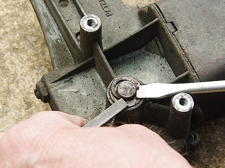
The first thing to do is remove the main gear. These are often seized in their bearing. Of course this stops the armature from spinning.
If you knock it out the bearing will separate from the casing. Don't panic if you do this.
It's also fairly common for the armature to be stuck.
Sometimes it's seized in the bearing in the gear-case. If you pull on it the self-aligning bearing will pop out of its spring. If you do this contact me and I'll help you get it back. Easy if you know how. Mess about and you will break the spring.
Sometimes they get rusted to the square body. Recoverable but often the winding will be impaired by water.
The pole-piece was bored in place. If someone who does not know turns it round, the armature will usually jam. Same thing happens if you swap the parts from one motor into another.
I could go on! Photo shows how I remove the C-clip to get the gear out. Watch it does not ping away.
-
-
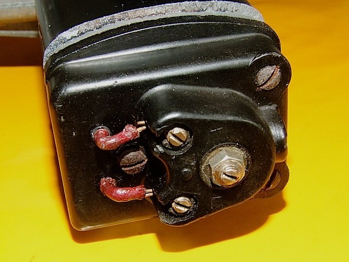
It occurred to me that you may not know how to connect this.
You must identify the GREEN wire. It will be soldered to the left-hand carbon brush. That's one battery connection.
Join the other two wires together, They are RED and BROWN. This will probably be hard to tell. This is the other battery connection.
If it does not run, DONT leave power on. You will burn out the armature in about 1 minute, because it will be taking at least 10 Amps.
-
75568 is sought after and fetch a good price, even if not working or rough. I can rescue these from the dead, they always go in the end.
75546 is a new number on me. 75446 is Spitfire or Herald or something. Worth about half as much a 75568.
-
-
Absolutely NOT. A TR6 wants a 115 degree gear. 120 would do at a push. !30 will put the blades off screen.
Anyway a TR5 used a square body type.
-
These take about 3A to run in, if in good shape. But there is a 10A surge at start. Modern electronic battery-chargers sometimes trip out because of this.
If you post the actual part numbers which are like 75XXX (and then a letter after which does not mean much that is interesting), I'll be able to tell you more about them and which is most likely to be useful.
You are looking for one with a 120 degree gear. The number is stamped on the gears.
Also for a TR250 should have three wires, not push on terminals.
The correct part-number is 75568, but these are rare and all sorts have been pressed into use.
I've rebuilt hundreds of these and have spares and such.
-
Sorry chaps I've not been keeping up on here. With the lockdown everyone is fixing their wipers and I've been inundated with requests.
Anyone who still needs a motor to be fixed should send a PM. These show up in my emails and you will get an answer.
-
Long been in use for repairs to circuit-boards. If you replace a track with a thin wire, because of damage or defect, you secure the wire with something very like this. It's usually green.
You can deposit really tiny amounts between the pads and solder a chip down using hot air after its been cured.
But you are right about epoxy. My wife chipped the rim of her favourite mug. Piece about 6mm diameter. Fine China mug. So I glued it back with Araldite not expecting it to last long.
Been in daily use for TWENTY years.
-
You probably can't get a horseshoe clip but an E-clip of the right size will work OK.
My usual source of carbon is out of stock, so the answer is China!
Normally I'd supply you but not at the moment I'm afraid.
-
So you are trying to bench test a reverse-parker.
You must pair up the connections to the brushes with the connections to the field-coil. The special switch normally does this pairing.
You will find a GREEN wire and BLUE wire that are connected together. Say you ignore BLUE and use GREEN
Pair the GREEN with the WHITE and this is the 12V feed to one brush and one field-coil end.
The other brush is the RED wire. Pair this with the other end of the field-coil which is usually BROWN and this is the OV supply connection.
If you can't be sure of the colours take of the end-cap and see where they go.
-
Roger is right. You want a 120 degree sweep gear in a DR3A for a TR4A. 110 degrees will do.
What colour wires do you have?
-
You will find everything you need here. You could ring and ask for help.
https://www.vehiclewiringproducts.co.uk/
-
75325 is a "reverse-parker" type from a Rover, P2 I think. These have the field-coil brought out separately. This is so they can be made to run backwards when set to park.
The gear will be marked 120 but this is the sweep angle when running. When set to park they run back by another 40 degrees, 160 degrees between parking position and extremity of sweep.
120 degree is almost too much for a TR so you will never keep the blades on the screen with that one. Oh and that's a single speed, 6-wire on the two-speed models.
So put that on eBay for about £50. While you are there search for 75568 which is the correct part-number for a TR4A two-speed.
-
The terminals just join your feed wires to the two wires sticking out of the plastic cap. On these little motors it's really easy to break something, like those little wires. So be careful.
The big screw is for end-float adjustment on the armature. If you have fiddled with this, back if off and re-adjust with the motor running.
If you have slackened the screws in the corners that hold the plastic cap in place you may find the motor won't go. This is because the cap has moved and jammed the armature. You have to find a "sweet spot" then tighten the screws. Great production technique. But then this is 1940's design.
I put them on 5V supply and jiggle for maximum speed. DONT APPLY 12V for very long if it does not run. You will burn out the armature.
By the way I've done two-speed conversions of these for a couple of Forumites. Worked OK.
-
His Ferrari has an aluminium floor and he uses pop-rivets because he's scared to TIG weld. This is because it has a lot of dodgy electronics which he thinks will get blown up by welding near it. Probably right.
-
There is a Youtube video of a guy repairing a crash damaged Ferrari, that he bought for 10K USD or so. There is a hole through the floor where it landed on a curb or something. He pop rivets an alloy plate over the hole. You can do many things in the US that you can't do here.
-
There are several ways to wire the switch which kind of work but really are wrong.
One has you parking at FAST speed which as mentioned above can mean that it jumps over the gap in the parker and goes off again or just parks past where it should do.
Another little variation has the motor behave perfectly but even in the PARK position current continues to run through the field-coil. It stops of course when you turn off the ignition but otherwise your motor is kept warm all the time.
You can also get it so that the switch gives PARK-FAST-SLOW rather than PARK-SLOW-FAST. This just means that you are starting the motor at reduced torque. A bit like pulling away in 3rd gear. Sometimes they stall if you do this.
If they stall and you don't get power off quite quickly you will get a "black-wire" armature.
Wiper motor testing
in General TR Technical
Posted
Deleted some old messages. Try again please.