


jwykes
-
Content Count
30 -
Joined
-
Last visited
Content Type
Profiles
Forums
Calendar
Posts posted by jwykes
-
-
Hello TR fans
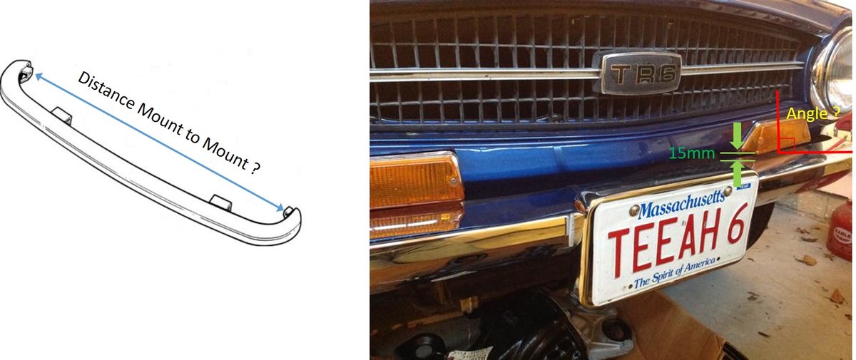
Progressing slowly with my TR6 rebuild I have started to assemble the front end. The car came to me in pieces and it looks like I have the early CP type front bumper. My car is an early CR.
Not a problem as both types of bumper should fit.
The problem I have is with the front bumper fitted it looks like the front end is too narrow. There is approx 1/2" gap between the lower wing and side bumper bracket on LHS and a generous 1/4" gap on RHS. The bonnet is on and even gaps all round, parallel to the front bulkhead so looks like there is no twist in front end.
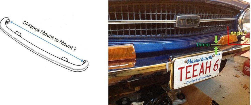
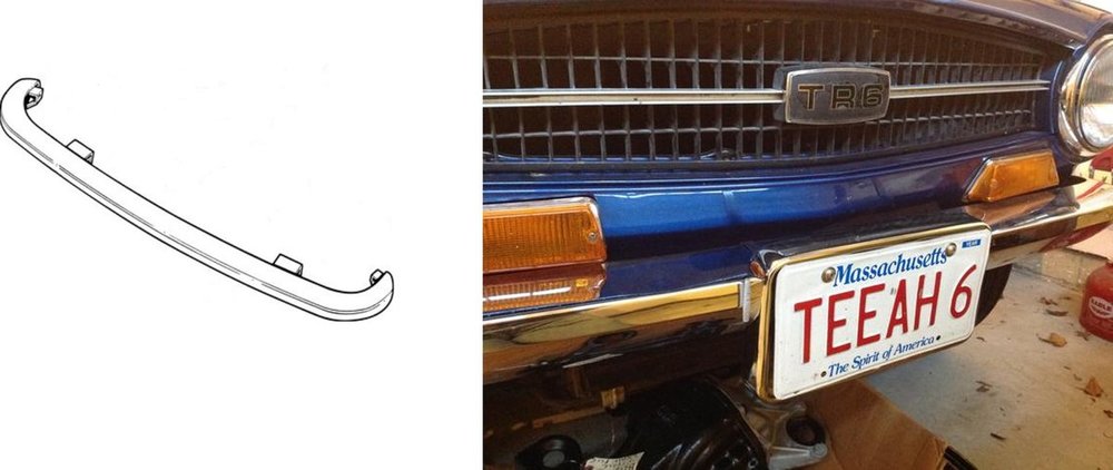
Fitting the front indicator units gives me another question. Should the lens face be vertical when looking from the side or sloping back, as it does on my car? I have approx 15mm between bumper and underside on the lenses. I've looked at lots of TR6 on the interweb with CP style bumper fitted and they all different.
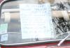
Can someone confirm what the distance should be between bumper side mounting brackets, as I have no pedigree of these parts. It doesn't look damaged, no obvious creasing. Made a photo of the things i'm looking for. If any one can help much appreciated.
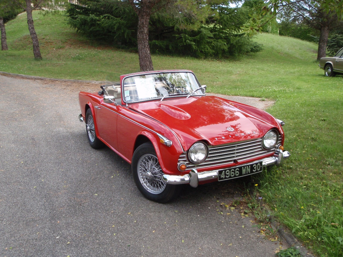
To save any confusion, blue car is not mine just closest I could find to my car.
thanks
James
-
I came across this paint on a Citroen forum, and wondered if anyone here has used it.
Looks like its a good base later before painting Bonda Rust Primer. Any thoughts?
https://www.youtube.com/watch?v=mn9eQrMW4qU
-
-
-
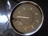
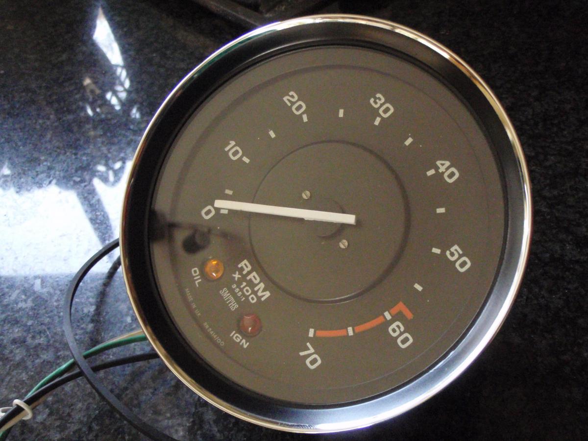
Hello Folks
I have been renovating my rev counter for a number of months now. 1st of all changed it from mechanical to electronic using the Italian kit. Next step which has taken some time was to replace the damaged and pitted bezels. News ones are available but they are all chrome and I like the original look.
So designed a paint mask in CAD and sent it off for 3D printing. Results of my efforts I have to say, is 9 out of 10 for originality.
Just need to finish the other 5 gauges and the rest of the car now.
Have a look at the attached for a few photos.
-
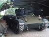
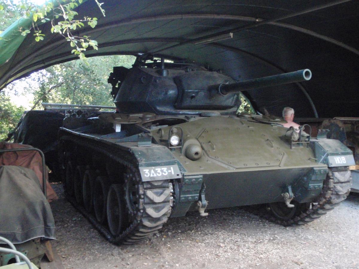
Bonjour gang
On holiday in South of France and called in to L'isle sur la Sorgue and spotted an Italian TR6, burble past. Still the tanks at the back of the gite takes some beating to
regards
James

-
Can I too express an interest please?
John.
Hi John
£45 for a kit including postage
regards
James
-
Hi there, I might just be interested, too. Depends on price.
Cheers,
Austin
Hi Austin
£45 for a kit including postage (would be a little more for post to France though)
regards
James
-
That is a serious piece of kit, James, can you give me a guide as to cost?
Hi
£45 for a kit including postage
regards
James
-
Steve
Sent you a PM
James
-
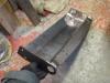
Just thought i'd share my latest piece of the TR6 restoration.
Like many cars out there the radiator shield has seen plenty of action over the years and needed replacing. My brother has tested his CAD skills and designed a replacement. Side pieces are 5mm steel so will be more up to the job if it ever needs a tow.
Finished welding it together today and i'm very pleased with the finished article.
If anyone is interested in a kit of laser cut parts, to weld together yourself please let me know.
regards
James
-
John
Yes i'm James
I used 20x40mm box section for the hoops and 2x25mm for the cross braces which bolt to the body. Need to improve the castor to frame securing method as I ran out of material.
Alex Falize was the source of this design, but I thought it was a little on the heavy side and the braces were not removable from the frame.
hope that helps
James
-
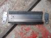
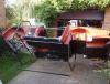 I've been busy fabricating a roll over frame for several weeks, to reach all those hard to find places on the body.
 I have impressed myself as I finished it today. The frame when attached can be easily rotated by pushing and holds the body secure. It will be useful to transport when its ready for painting
Just back to underseal scraping and more welding.
Have a look and see what you think.
Its been done before I know but my frame is lighter
-
I had a similar problem a few years ago on my Spitfire. Try cleaning the bullet connectors to the front indicator / sidelight units.
May not work, but worth a try
regards
James
-
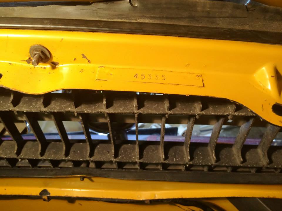
Andrew
This is the plate I noticed on your car. Should this be fitted to all TR6's?
regards
James
-
That settles it, red it is for my car.
Noticed on the photos for DPF there's a body stamped plate above the front grill. Should this be on all TR's?
-
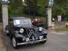
Cruising through southern France today, came across a couple of gems for sale just outside a village called Barjac.
TR4 and Citroen Traction Avant if your interested
enjoy
James
-
Spotted one of our Dutch TR6 fans today near Vallon Pont d'Arc in the Ardeche.
My co pilot managed to take snap. Anyone recognise him?

-
Does anyone have any knowledge of the inner wing panel offered by Revington.
How does it fit and look compared to a heritage panel or the handmade type Rimmers sell (before they ran out of stock)
thanks
James
-
Does anyone out there have this car?
Just been given a workshop manual and theres an envelope with MOT's and receipts. Free if anyone wants them
regards
James
-
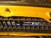
Folks
I'm in the process of replacing the LH floor, inner and outer sills. Both ends of the inner sill and floor have dissolved due to tin worm.
Question I have is what are the actual number and position of the harness bendy tabs. MOSS book say's as required. My sill has 3 remaining but should there more?
A photos would be great.
regards
James
-
Or look at this link from Alex Falize. As long as the floors and sills are sound it looks to be a really neat idea. May have a go with my own project.
regards
James
-
Thanks Darren.
The car didn't have a front end when I bought it, so it make panel alignment and gaps more of a challenge
regards
James
-
I have now taken the plunge and welded the replacement front valance panel to my TR6. Refitting the front wings shows some panel fettling is required.
Does anyone have close up photos of the wing headlamp panel to valance? Want to understand how far out my panels are.
thanks
James


TR6 inner wing panel - NLA
in TR6 Forum
Posted
On my slow rebuild I reached the point where the RH inner front wing needs replacing.
I replaced the LH with British Motor Heritage part couple years ago after unsuccessful trying a pattern panel. I now find out BMH panels for inner wings are no longer available. I phoned them up and to say their response was lacking any passion for their industry was an understatement. No interest in reinvesting in the presses on a part that in prone to accident damage. If there was no demand for them the shelves would be full of their unsold panels surely?
If this continues all they will sell is oil and keyrings for cars wanting replacement panels.
Any thoughts on which repro inner wing is a better fit or do they all come from the same place?
regards
James