


Fred Winterburn
-
Content Count
28 -
Joined
-
Last visited
Content Type
Profiles
Forums
Calendar
Posts posted by Fred Winterburn
-
-
1 hour ago, stillp said:
They certainly are cold welded, if done correctly. Most however aren't.
Pete
Which includes any I have ever taken apart which is many, either done in a factory or by hand. Not to say that it couldn't happen.....Fred
-
1 hour ago, stuart said:
The gold plating actually does make a difference, all military spec wiring and BBC studio wiring uses it.
Stuart.
Then we could really go off topic and argue whether crimped connections are actually 'cold welded' and 'gas tight' like some publications indicate
")
Fred
-
10 hours ago, ctc77965o said:
The arcing of the points weakens the spark, the condensor acts to reduce the voltage spike across the points, that reduces the wear on the points and also strengthens the spark.
https://en.wikipedia.org/wiki/Delco_ignition_system
If you find that theres metal build-up one side or other of your points, thats a tell-tale that the condensor is not matched to the coil. A condenser with too much capacitance will cause a build up (metal transfer)on the mounting side of the points. A condenser too little capacitance will cause a build up (metal transfer) on the arm side of the points.
I've actually tested this because I wanted to know why points burn on the other contact when a too-large condenser is used (and yes I'll keep calling it that because historically that is what it has always been called). Without a scope you would never see why and it doesn't make sense on the face of it that points would burn on the opposite side just because the condenser is made larger. When the condenser is sized too large, the no-load (no spark) sine wave that begins when the points open, reduces in amplitude (lower voltage) and also decreases in frequency (the period is longer). Because the available voltage is lower, under compression the percentage of misfires increases (where no spark forms). If the spark is struck, all is well as the no-load sine wave exists for only part of the first 1/4 cycle and then the energy dissipates quickly within the system and the spark channel. However, if the available voltage isn't high enough which can easily happen at mid range rpm where the dwell is reduced (less energy also equates to lowering the amplitude of the no-load sine wave) with the engine under load, misfires result. Perhaps not enough to be felt in seat of the pants testing, but they can be there nevertheless. On every misfire energy is bottled up in the system and the sine wave continues with energy oscillating between the coil inductance and capacitances in the circuit including the condenser. The energy does decay in a typical 1/4 decay, but the lower frequency keeps the energy in the system longer. The timing is such at mid range rpm that when the points close, that coincides with a portion of the sine wave driving current in the opposite polarity to when the points open. Even though the percentage of misfires can be quite low, and the energy is reducing by 1/4 decay, the pitting is bad because the arc intensifies with the closing of the points. It is this current flowing in the opposite direction on points closure that causes metal transfer to the other side. I did the testing on the same test rig my father knocked together in a hurry probably in 1961, possibly 1960. (see Wikipedia on Capacitor Discharge Ignition and look at the homemade rig that Lloyd Winterburn was using) For my test I doubled the condenser value to 0.44µF and opened up the spark gap wide enough that there were misfires occasionally at approximately 2000rpm (8cylinder). Then I opened up the gap so wide that there were misfires 100% of the time and had a good look at the scope. It's been awhile since I did that experiment but I believe the points closing coincided with the 2nd positive peak on the sine wave. If the condenser is sized properly at about 0.22µF, there won't be burning of the points when they close, or extremely little burning of the points. This is because the frequency is higher and the energy dissipates fast enough that by the time the points close there is very little left over. Fred
-
Not too many engines will run without the condenser. If the engine is already warm and the plug gaps are extremely small, there might, just might be enough spark to make the engine run, albeit very badly. Normally condensers go open circuit and the engine misfires like crazy. Open circuit is the same as taking the condenser out of the circuit. The condenser does more than keep the points from burning. To put it simply, it prevents energy loss through the arc and in doing just that, it ensures there is enough available voltage to fire the plugs. Fred
-
On 9/30/2020 at 5:26 AM, RobH said:
The condenser and lead(s) inductances are a series resonant circuit. Ignoring the internal inductance of a wound condenser the standard lead length gives an inductance of around 30nH which with a 0.22uF capacitor resonates around 2MHz. If the lead length is 10cm the inductance is circa 100nH and the resonance comes down to 1MHz. With a 30cm total length the resonance is around 600kHz.
A series resonant circuit becomes high impedance at the resonance which prevents current flow so it is entirely possible that longer leads will affect the suppression properties if the spark frequency is near the resonance.
Rob, and anyone else interested. I've been scratching my head on this one for some time. The problem is the frequency of the no-load sine wave when the points open is about 2.5 kHz, way below the resonant frequency that any added lead length could possibly give. I know for a fact that long lead lengths from the points to the condenser does indeed increase the arcing at the points. Roughly 15% more arcing with an extra two feet of wire. I've finally found an article that explains it. It is not addressing condensers in cars, but transient voltage suppression devices. Please see the attached article. Fred W.
-
15 hours ago, Lebro said:
Probably to suppress radio interferance from ignition.
Bob
Yeah, Probably a radio noise suppression capacitor. Presumably connected from the ignition switch side of the coil to earth. Ford used to do that back in the day and a few others. Fred
-
If you go for an alternative condenser, keep the lead lengths as short as possible. Adding a foot or two of wire reduces the effectiveness in arc suppression considerably. I was surprised that it makes as much difference as it does keeping the lead lengths short. A good type of capacitor that can be soldered inside a gutted Lucas shell is a modern high voltage ceramic type. I suggested a Kemet capacitor in this MG forum thread (link below). Now unfortunately, the Kemet capacitor is now obsolete and getting hard to find, but there is another by Murata, part number RDER73A224MUE1H03A that should work well too although I have not tested that one specifically. If you wade through the pages on the MG forum you will see the testing I did. The Kemet capacitor has been in use in a great many cars now. The hardest part of doing the retrofit is gutting the old case. I used a small flat bladed screwdriver and only stabbed myself once on the first one I did. https://www.mgexp.com/forum/mgb-and-gt-forum.1/condenser-retrofit-capacitor.3580196/ As an aside, a multimeter with a capacitor function will not tell you if the capacitor will function properly under high voltage and current conditions. A real condenser checker thumps the condenser hard with both high voltage and high current. Without a condenser checker the only really good way to know is to substitute with a known good condenser. For fun here is an article I wrote on the function of the condenser. Fred
-
CDI can have drawbacks if done badly, but has several advantages if done right regardless of what is used for the trigger (points or whatever). Inductive ignitions have a horrible phase lag between voltage and current so the voltage has to rise much higher to provide the required current for spark breakdown. This results in a large voltage overshoot, and a less powerful spark due to the fact that current and voltage are so out of phase with each other. CDI has a leading power factor with current rise actually peaking before voltage peaks but with the two being closer in phase (much closer than inductive ignitions). The total peak voltage and any overshoot as a result is determined by the voltage the capacitor is charged to, times the turns ratio of the coil. Since the power is higher (due to a favourable phase angle) high voltage is not needed for spark breakdown. Secondly, the leading power factor makes a CDI almost immune to a shunt resistance since the spark gap prior to breakdown behaves like a capacitance which prefers a leading power factor. It's for this reason, not a fast voltage rise as is universally written (except by me) that makes CDI so great at firing fouled plugs or firing the spark gap with other shunt resistances such as wet plug wires or wet and dirty spark plug insulators. Here are a couple of articles explaining voltage overshoot and one explaining the real reason for CDI superiority in firing fouled spark plugs. At some point I will re-write the article into one article with phase angle being the common reason for most of the differences between CDI and inductive ignitions. It explains both the voltage overshoot to some extent and also the ability to overcome shunt resistances that would otherwise lead to no spark at the plug gap. Fred
CDI Superiority in Overcoming Shunt Resistances.pdf Ignition Voltage Overshoot.pdf
-
Hello Roy, I posted a message to this forum about 3 years ago on what I discovered wrong with my TR3 water pump. I found that the end clearance between the pump impeller and the engine side of the pump housing was very large. So large in fact that the pump would not operate as a pump at idling speed. I fit a spacer inside the pump housing to correct the end clearance and the flow was increased infinitely at idle and many times more at higher pump speeds. On the older pumps, the impeller will move easily enough on the shaft so that the clearance can be adjusted, but on the County brand pump I bought, the impeller wouldn't budge even with some heat which is why I used a spacer in the pump body instead. My old pump and the County pump had clearances of 75 thousands of an inch. I decreased that to 7 thou with the gasket in place. Anything more than 25 thou space and your engine will be relying totally on thermosyphoning while at idle. Which is why huge radiators and electric fans are so beneficial. A good pump will make up for most deficiencies and no electric fan is required in most climates. I would suggest that a fancy curved impeller won't work any better than the old 4 straight vane variety if the pump end clearance is too large either. I went one step further and modified the pump housing to distribute some flow to the rear drain petcock via and external hose. It also makes a very measureable difference and my engine runs cool now front to back, but just fixing the end clearance is likely enough if your engine is good and clean inside the liner area. (mine wasn't after years of abuse and very few coolant changes). Also, on my county brand pump I could not get the woodruff key to stay in place while I tightened the nut, so I discarded the key and crossdrilled the nut and shaft and put a cotter key through the nut and shaft after tightening the nut. By the way, my TR3 engine resides inside a 56 Morgan Plus 4 which has a radiator about 1/3 smaller than the TR equivalent. The rad is plenty big enough on a Triumph despite what I have seen written. In my opinion most of the issues can be traced back to the end clearance problem. Good luck, Fred Winterburn, Ontario, Canada
-
You're welcome Bill. I think you will be impressed with those fasteners once you see them in person. When I finally get around to rebuilding the engine on my 56 Morgan I'll most definitely be using an ARP kit for the head as well. Those are lovely old engines despite the odd minor flaw. I love the torque and the hiss through those twin SUs (no filters on my car--at least not yet). Lots of fun. Take care, Fred
-
Bill, Maybe a little late with this. Consider using ARP studs when you do the repair. This problem has happened to several owners of TR3/4 powered Morgans as well as Triumphs over the years. It is a common enough fault. I think Ken Gillanders of British Frame and Engine in the US is the only one that carries an ARP kit for this application. I used them on my TR3 engine for insurance against exactly what happened to you. Also, follow Ken's advice on how much to torque the ARP stud nuts. Anyway, it is a band aid cure for a poor pedestal design common to many British engines of that era. The foot of the pedestals extends towards the valves when it should extend the other way. Also, a good pedestal design has the rocker shaft pinned to it by the stud. That way if one pedestal decides to 'rock', the shaft must also twist in response as opposed to just bending. This makes the shaft less prone to deflection and distributes the stress to the other pedestals as well, which strengthens the whole assembly. To see better designs, look up pictures of the Rover/Buick 215 shaft assembly, or the Volvo B18/B20 series rocker shafts. Good luck, Fred Winterburn, Canada
-
Littlejim,
You are too kind. I'm not in that esteemed company. I have a friend who was stranded on the side of the road with a sixties vintage Datsun (can't remember the model). He determined that he wasn't getting fuel and that the pump which was a sealed unit had failed, but it was a valve inside the sealed unit that wasn't working, not the diaphragm. He hitch hiked up the road to a gas station and bought two PCV valves and enough hose to do the trick. He plumbed one in at the inlet and another at the outlet, since he didn't know which valve had failed. These two check valves allowed the pump to work and he made it home. Then there was the Eskimo that was stranded in the far north with a broken spring on the points for his snowmobile engine. He whittled a new one out of a piece of whale bone, and he too made it home, alive. Nope, I'd have hitchhiked all of the way home and spent two days getting the old car going, or frozen to death on the Tundra. Thanks though, Fred
Fred,
I think you are on the way to qualifying for the 'bush mechanic's' hall of fame.
One of Oz's best wrote a book 'Son of the Red Centre' about bush bashing by truck in the Top End early last century before there were any real roads. During one stop he was cleaning the clogged carby in the middle of nowhere and when he swatted a cloud of bush flies off his face lost the float needle in the spinifex.
He whittled a replacement one out of a mulga root and continued his journey to Darwin.
-
James,
I really should keep my mouth shut as I don't even own a Triumph, but I fear that you have found out the hard way the nature of all of these forums. There is the good and the bad. You were bitten by the 'old guard'. I personally do not care when you joined as I'm sure there is not a seniority clause. Your posts were all polite and should have been treated with more respect by some. Please don't let any of this detract from your hobby. Focus on the machinery, not the people. People and British cars will always let you down, but you can fix British cars. Take care, Fred Winterburn, Canada
Exuse me sir. If you really dont mind, i was just asking the history of this triumph. I like learning about this topic because it interests me. I respect
Graham's privacy as well as yours. Yes, I have learned many interesting things on this forum and I don't think I was asking to much. I guess personalities are different over here in The States. Whats the point of having an historical Triumph? Well it's your choice, but I think its nice to share the history of them. I'm not trying to start an argument here, but I have learned from you that it is not my affair with Graham. Now i want you to learn something. Dont take things so seroiusly in life. Life is too short, enjoy it and share it. I never meant for this little thing to change your decision. Heck! I say have fun with your Triumph no matter what anyone says.
Best Regards James
-
I realized that I made a slight error in my post. I said:The hole through the float chamber is now slightly less than 1/2 inch diameter, and the grommets hug the bolt tightly for a good seal. I should have said the hole is slightly smaller than it was previously. I didn't actually measure it. Fred
Hello Folks,
I finally had enough of my front H6 carburetor leaking where the float chamber attaches to the carb body. I've gone through two new sets of the rubber top hat shaped grommets which I'm convinced were made just a little too small. The last fix I used was to add a small diameter O-ring between the rubber grommets to stiffen the whole assembly somewhat but not interfere with fuel flow. This fix lasted one year until it started leaking again last night.
For some reason the hole through the front float chamber was made ever-so-slightly larger than the same hole on the chamber for the rear carburetor, by just a few thousands of an inch. Manufacturing tolerance I presume.
Today, I sleeved the float chamber hole with a short piece of 1/2 inch copper pipe. I reamed the existing hole in the float chamber slighty larger, such that the copper pipe would be an interference fit into the hole. I cut a piece of copper pipe slightly longer than the length required, and drilled a hole in the side of it to line up with the gasoline entry hole in the float chamber. I filed a slight taper on the leading edge to get it started in the hole and then pressed it into place so that it was sittling proud on both sides. I then trimmed it carefully on both sides. The hole through the float chamber is now slightly less than 1/2 inch diameter, and the grommets hug the bolt tightly for a good seal. With a bit of oil to ease assembly it went together well and doesn't leak. For now anyway. The float chamber doesn't flop about as easily anyway so I have some confidence it will work. Take care, Fred Winterburn (1956 Morgan Plus 4)
-
Dave,
The distance ring is just a plain old steel washer that I bought from my local farm supply store. I had to turn it down slightly on the outer diameter so that it would fit into the recess in the pump body. The rivets are carbon steel as well. I did use JB Weld brand epoxy to help keep it in place, but I think this was totally unecessary. The rivets go right through into the suction side of the pump housing. I can't remember exactly how long the rivets were, but they just went through to the suction side. You're right, almost any material would do, and with a good 50/50 mix of antifreeze solution, there should not be any corrosion issues. To determine the end clearance, I used plumber's putty which I peeled out and measured with a set of dial calipers.
The washer I used had an inside diameter that was slightly smaller than the original hole for the 'suction eye', but as long as it is not too small, it shouldn't matter. And quite frankly, in my opinion the original hole is a little large anyway.
Dave, if you did decide to go the whole nine yards, and make a back pressure plate like I did to force some flow to the rear, make it out of thinner material than I did. I used 1/8 aluminium plate which offsets the water pump pulley from the generator and crankshaft pulley by the same amount. I'm sure this offset won't matter as I've seen much worse on other engines without belt wear or bearing problems, but thinner would be better. Next time I would have used a thin piece of epoxy glass circuit board material I had lying around. Still, I'm happy with the present arrangement.
What I would like to see, is a company like Racetorations in the UK for example, make pump housings with little or no clearance, and provide gasket shim kits with them so the owner can 'clearance' the impeller correctly. Take care, Fred
Hi David
Funny how silly things slip your mind. I only had the engine running a few minutes when I looked in the neck, certainly not long enough for the temp. to come up to normal running, so that is something I must do again.
Fred
I understand that you used countersunk rivets in the housing, but how long were they? as I assume that they were blind holes. Also was the distance ring made of stainless steel and also the pop rivets, surely aluminium wouldn't be strong enough, and did you lock them in with loctite or the likes?
-
Hello David, You asked: Fred - Your solution with the pump impellor seems logical, but how does it miss the heads of the pop rivets? Also the mod to the petcock and the pump seems a good idea to get extra water to the number 4 cylinder.
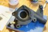
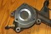
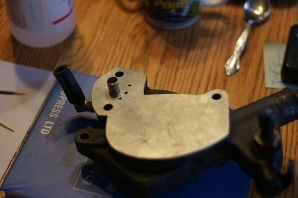
David, I suppose the picture does not show it well, but the 77 thou thick washer was held in place using tapered head pop rivets and I counter sunk the holes for them to fit flush using a larger sized drill after drilling the usual 1/8 inch holes. With a slight bit of emory to smooth down the rough spots, the rivets only sit proud of the spacer by about 1 thousands of an inch. Take care, Fred By the way, with this modification and the back pressure plate to proportion some of the flow to the rear, if I open the rear petcock with the engine running and stone cold (before it has had time to pressurize from heat), the coolant will spray out like crazy at idle. Lots of pressure available with the 'new' pump.
-
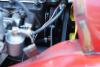
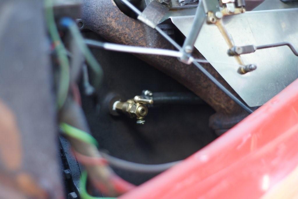
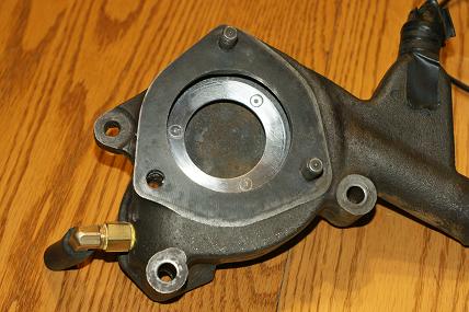
Dave, Here are the rest of the pictures of my modifications. The one picture shows my back pressure/nozzle plate. This does restrict overall flow slightly, but since the pump is working properly after the end clearance was corrected, this doesn't matter much. The nozzle plate allows about 1/5th of the flow to go to the rear which helps cool #4 and #3 cylinders. The nozzle helps jet some water towards #2 cylinder liner, and the small holes ensure that #1 cylinder liner is cooled at the front, and this was a good way to fine tune the front to rear flow ratio as well. The pump housing tap-off is a barbed elbow with a 1/4 inch pipe thread. There was lots of thickness in the cast iron to do this. I discarded the brass union seen in the one picture on the water pump discharge in the final assembly and just used the hose barbed elbow. For the rear petcock, I ran a 1/4 inch pipe thread tap (same as pump housing tap-off) into the old threads to clean it up and give them a taper for the brass fitting used to tee in the hose connection. Hope this helps out. Fred Winterburn.


-
Hello Dave,
I made a post last year outlining the cooling system modification I intended to make to my 1956 Morgan with a TR3 engine. My engine used to overheat terribly. After a hard run the engine would spew coolant out of the overflow pipe (4 pound pressure cap) and gurgle as steam formed and collapsed. I believed the problem was a flow distribution problem and decided to tap off the discharge of the water pump housing and feed coolant to the rear petcock. In experimenting with the pump, I discovered that the impeller end clearance of 75 to 80 thousands of an inch is ridiculously large. The pump would not pump at all at idling speed and was marginal at any speed. I corrected the end clearance by installing a 77 thou washer riveted in place with flush pop rivets (see picture), and with the gasket the pump end clearance is now about 7 thousands of an inch. The pump now pumps like a pump should, and I'm using the standard, cheap 4 bladed pump. My cooling problems are gone. I did install a back pressure plate to allow 1/5th of the total flow to the rear petcock as this is what I set out to do originally, but in actual fact, just fixing the pump might have been enough. The usual fix of installing an electric radiator fan only enhances the thermosyphoning that these engines must do to keep cool in the absence of a good pump. With the end clearance corrected, the pump will work at slow idle and will be at least eight times more effective at 1500rpm from my experiments. To give you an indication of how well this modification worked, the other day it was 27 celcius here in southern Ontario Canada (which is warm for May), and I took my old car for a hard run for 3 miles at 95 MPH. I pulled over immediately and shut the engine off right away. No noise and no coolant spewing out from the overflow. The firewall temperature was so cool I could hold my hand on it, as the underhood (bonnet) temperature was way down from previously. Bear in mind too that the Morgan radiator is 1/3 smaller than its Triumph counterpart, and the fan is quite a distance from the radiator. My cooling system is bone stock aside from fixing the pump and distributing some of the flow to the rear petcock to keep #4,3 cylinders from boiling. If you have time before your trip, I would look to your pump and correct the end clearance and shim the pump with gaskets such that the impeller is just free to move. It needs to be small, as even 30 thou is a ridiculously large end clearance for a centrifugal pump that tiny. Good luck, Fred Winterburn, Ripley, Ontario, Canada


-
Hi all
I am having problems with a needle valve sticking in my rear carb, have spoken to burlen and they have recommended new needle valves - apparently they have a rubber pin that is more accepting of tiny bits of dirt. I am off to burlen first thing tomorrow to collect them.
However, this has led me to think I ought to put an inline filter in the fuel line. has anyone done this - what type was it and would you recommend it?
Hi,
As mentioned an in-line filter really helps, but I've had junk get into the float valves after storing a vehicle if the petrol starts to break down. One improvement I've made to all of my SU carbureted cars is to replace the standard float valves with 'Grose jet' brand float valves. They are not nearly as susceptable to a bit of dirt. Moss and others carry these American made float valves that use a stainless ball inside a brass body. They work extremely well. They can be overcome by too much fuel pressure, but if you are using the correct fuel pump this will never happen. Good luck, Fred
-
Hello Rod, I have a TR3 engined car that is bone stock and also suffers from overheating after a brisk run or at stoplights. I believe that the problem with these engines is twofold but can be traced to the same cause. Poor flow distribution as the poor flow from the pump 'wafts' through the hole in the block effectively cooling only #1,2 cylinders to the thermostat setting as the flow bypasses most of #3 and #4 cylinders. That and the fact that I discovered this last week by experiment, that the standard pump with 85 thousands of an inch end clearance does not pump at all at 500 RPM pump shaft speed. In fact, just to get it pumping takes 900 RPM pump shaft speed and then if the speed is slowly reduced to 600RPM, the flow stops completely. I made a washer 77 thousands of an inch and used JB weld and 3 rivets countersunk, to affix it to the base of the water pump housing. This makes clearance on my pump about 8 thousands of an inch. I performed the test again, and flow starts at 500 RPM and is at least 4 times the flow it had just above 600RPM before the modification, and at least double the flow at 900RPM shaft speed. It is now works like a pump should, and this was done with the standard 4 vane impeller. With extra pressure and flow, the back of the engine should see more coolant and have fewer hot spots and boiling. Boiling produces vapour, and just like air, this robs 'pressure energy' from the system which reduces flow even further. I'm going one step further, and have made a backing plate for the pump housing that contains a nozzle and some smaller holes. It's function is to provide some back pressure to force coolant through a penetration (1/4 inch pipe thread elbow, and a hose barb) I've made in the discharge side of the housing to distribute some flow to the rear petcock hole. I have diverted by this method, about 1/6 the flow to the rear of the engine without reducing overall flow by much at all. With the pump clearances corrected, it will still have at least double the flow it had before anyway. The nozzle should force more flow by #1,2 liners and still have adequate flow to the front of #3 liner. The small holes drilled in the 1/8 aluminium backing plate were used to fine tune the flow ratio, and ensure that the front of #1 cylinder gets adequate cooling too. I'll be installing this next spring and testing its effectiveness at that time. Hope this information helps, Fred Winterburn (owner of TR3 powered Morgan, serial #3504) Ripley, Ontario Canada
Just an added note. I will be replacing the original water pump with the aluminium gold anodised impeller (it was the kind with a roll pin rather than a woodruff key) with a County brand pump with a cast iron impeller. The County brand pump has the same end clearance as the original, but is 50 thousands of an inch larger diameter, so it should be slightly better than the original, or at least no worse. Fred
-
Hello Rod, I have a TR3 engined car that is bone stock and also suffers from overheating after a brisk run or at stoplights. I believe that the problem with these engines is twofold but can be traced to the same cause. Poor flow distribution as the poor flow from the pump 'wafts' through the hole in the block effectively cooling only #1,2 cylinders to the thermostat setting as the flow bypasses most of #3 and #4 cylinders. That and the fact that I discovered this last week by experiment, that the standard pump with 85 thousands of an inch end clearance does not pump at all at 500 RPM pump shaft speed. In fact, just to get it pumping takes 900 RPM pump shaft speed and then if the speed is slowly reduced to 600RPM, the flow stops completely. I made a washer 77 thousands of an inch and used JB weld and 3 rivets countersunk, to affix it to the base of the water pump housing. This makes clearance on my pump about 8 thousands of an inch. I performed the test again, and flow starts at 500 RPM and is at least 4 times the flow it had just above 600RPM before the modification, and at least double the flow at 900RPM shaft speed. It is now works like a pump should, and this was done with the standard 4 vane impeller. With extra pressure and flow, the back of the engine should see more coolant and have fewer hot spots and boiling. Boiling produces vapour, and just like air, this robs 'pressure energy' from the system which reduces flow even further. I'm going one step further, and have made a backing plate for the pump housing that contains a nozzle and some smaller holes. It's function is to provide some back pressure to force coolant through a penetration (1/4 inch pipe thread elbow, and a hose barb) I've made in the discharge side of the housing to distribute some flow to the rear petcock hole. I have diverted by this method, about 1/6 the flow to the rear of the engine without reducing overall flow by much at all. With the pump clearances corrected, it will still have at least double the flow it had before anyway. The nozzle should force more flow by #1,2 liners and still have adequate flow to the front of #3 liner. The small holes drilled in the 1/8 aluminium backing plate were used to fine tune the flow ratio, and ensure that the front of #1 cylinder gets adequate cooling too. I'll be installing this next spring and testing its effectiveness at that time. Hope this information helps, Fred Winterburn (owner of TR3 powered Morgan, serial #3504) Ripley, Ontario Canada


Are crimp connections really cold welded?
in TR4/4A Forum
Posted
This was discussed in the condenser outside the distributor thread, but I thought it would make sense to start it over here. I must say that I have taken many crimps apart and have never seen any evidence of cold welding. Just tight mechanical connections. I'm not saying it doesn't happen, I'm just saying it likely doesn't happen very often. I've attached an old article (there are many others out there) that purports that the low to nil voltage drop of crimp connections over time is due to there being sites that are cold welded within the joint. However I've seen wires twisted together and covered with tape that several years later did not show any voltage drop even with considerable amperage through the circuit. Yet, I have seen many corroded and high resistance crimps from the wire to connector interface especially in automotive wiring. I like soldered joints for this reason, but crimps sometimes are the only practical alternative in which case I seal them with dielectric grease to keep salt and moisture out. What are other's experiences here? Real personal experiences, not references to oft repeated lore or other publications if possible. Fred
whitleycrimptheory_p142-74.pdf