


simon iregbu
-
Content Count
118 -
Joined
-
Last visited
Content Type
Profiles
Forums
Calendar
Posts posted by simon iregbu
-
-
Simon,
if your coming here for spare parts inspect each and every item on the shop counter as there quite a few iffy parts floating around.
Roger
Roger,
The spare that I was originally coming for, are for my TR250, brake pipes (as they want an arm and a leg here for the copper/nickel stuff) and electrical items. The o-rings would be an addition, but thanks for reminding me as I had not thought of that till you mentioned it.
Simon
-
Are the butterflys perfectly synchronised? If they are not all opening at exactly the same time, low speed running will suffer.
A couple of years ago i spent a considerable amount of time ensuring that they were as i had an idle issue, so they should be but I guess that I may need to check this out again.
thanks
Simon
-
Guy
I do have the small circlips on the injectors, I will check them out. unfortunately this will not be for a couple of weeks as I will be in the UK
for a couple of weeks doing business things. I will also be stocking up on spares while I am there so maybe I will get some new o-rings whaile
I an there.
Simon
-
Has the car always done this or is it a recent evolution?
If the former and the car has had lightened flywheel or other go faster (higher spin/revs) mods low rev range is lumpy and gutless, sometimes termed off the cam, once loud peddle suitable caressed grin expands as the GGGGGGGGGGs push on.
If symptom is recent then its another issue..
I would have to say that this is a recent issue, the car is 'standard' in that I have not done anything that would improve the performance.
-
Thanks for the replies,
Robin
The inlet butterfly's & spindles are new, I got the underslung kit from Malcolm fitted. I have tried adjusting the timing and there was no difference either. I will try another rotor arm as I have a spare, but the spare could be bad so I may have to get one from Martin (distributor doctor) then I know it will not be that. I checked the plugs last night and all of these seemed to be okay (i.e. all the same colour, gaps, etc.). I also have a Pertronix ignition so no points.
My main thought was that it was the injectors so I will check these later, I have checked for the spray previously and this was okay but not to see if they rattle. Guy I will dod a search later, I have a car show to go to today, but I assume that you can here the rattle with the engine not running and while there is still pressure in the system?
Simon
-
My 1973 TR6 (PI) has the occasional 'misfire' which only seems to be when pulling away from the lights in a nice steady fashion up to ~2000rpm. As the revs get above ~2000rpm then everything is great and it runs smoothly. As I have not driven the car a great deal this summer so I have not been too bothered about this, also when I do drive it all I can say is that there is a really big smile on my face
so it is not too much of an issue. I am tempted to think that it is a blocked injector/faulty plug or bad spark plug wire. I would like to figure this out before I put it into storage for the winter.
Does anyone else have any other ideas as to what could be causing this.
Thanks
Simon
-
Dave
I believe that you have fitted this the correct way, because as the pressure builds inside the m/c the seal lip will be forced against the cylinder wall. If you fit this the other way round (i.e. smaller end of the taper facing front of vehicle, when installed) the as the pressure increases it could leak past the seal. So unless when installing you have damaged the
seal or the bore of the m/c is scored there should be no leakage. I know when I did my m/c I distinctly remember there was a concave side to the seal, this should be facing away from the shoulder of the plunger.
Simon
-
The cotton covered resistance wire should be about 10 Ohms, and can be replaced by a wirewound resistor if the cotton has rotted.....(mine was
)
I guess that 8.8ohms is okay then? Everything else looks okay (no open circuits), all I have to do is solder in some new wires. Thanks for everyone's input.
Simon
-
Guy
You could always make them up yourself, I re-did all of mine with the Cunifer (Copper/Nickel) pipe. I bought a length of pipe and all of the brass fittings and then measured the length of each one I took off so that I could make the new ones to the correct length. I also bought the pipe flaring kit so that I could make the ends correctly (the kit has had extensive use fixing the brake lines on my wife & sons cars). Cunifer is really easy to work with compared to steel, especially when bending by hand.
To create the bends in the right place I would use the original as the template and tape one end together, then bend the new pipe to the old taping it together as I went along. Then when you fit the new pipe in the car there is only minor tweaking to do to get it to fit perfectly.
I have just bought 25ft of pipe from vehicle wiring products, see link Brake Pipes
Simon
-
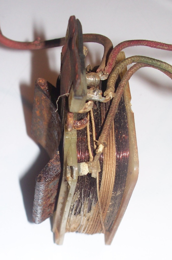
Hi Simon,
The coil you show has a lighter section of about 10 turns - this is the resistor that I alluded to, and that tells me that this coil is definitely from a two speed motor.
Where the resistor wire connects to the darker coil is where the other wire should be connected.
It's a little late for me to generate a diagram tonight, but if I have time tomorrow, I'll attach one)
TT
Looking more closely at the connections and reading you reply , one end of the insulated winding goes to the red wire with the brush terminal and park
switch wire. The green wire to the other brush terminal and has one end of the winding that (in the picture) disappears behind the metal half round metal
piece. The other wire (brown has one end of the insulated winding and also the main winding. so I think that everything is correct.
Is it possible to check that the windings are okay?
Thanks
Simon
-
Hi out there. My 1971 TR6 (150bhp) has a seized Lucas 22D dizzy and need to find a replacement. My seized unit has the part number 41219 stamped on the side. Can I use any 22D dizzy such as part nos 41501, 41542 etc as a replacement?
I also have a 1973 TR6 (125bhp) with dizzy part no 41501 and wondered if they are interchangeable?
Hope someone can help.
Thanks,
Roger
What has seized about it, I managed to completely disassemble mine as it was in the box of bits that came with the car so was not spinning at all. It was not difficult to take apart as long as you are careful. You could send it Martin (Distributor Doctor) and I am sure he could fix it for you if you do not want to attempt yourself. I am not sure on the differences but the counterweights and springs used to control the timing advance would most probably be different. You could always swap the internals if you have a spare lying around to keep the timing correct.
I guess that there would be no great harm in just swapping the distributor over apart from some loss in power. I am sure that someone else will be able to shed more light on this.
-
In picture 8 the rev counter is close to 2000, a little high I would say, carbs?? and a non-UK rocker cover, it looks more like the ones
used in the US. No sill trim, rear back panel body coloured. The fuel filler cap is same as those used in the US.
If this has only 17000 original miles why has it had a full respray (nice paint job by the looks of it).
I agree in that this looks like a LHD conversion. If it was originally a UK car there you would want to put up all the relevant
information. The lack of it leads me to think that its not as it first appears.
Simon
-
Simon,
I am not into electrics so unfortunately cannot answer your questions about the wiring - I am sure others with more experience will pick this up.
However I think I can clear up your point about the lack of wires coming out of the Herald wiper motor.
The two speed wiper motor originally fitted to the TR5 was a DR3A, part number 75568B - this number should be stamped in the same area as the DR3A, thus you can confirm that you do have an actual TR5 motor, also you will find other sets of numbers e.g. 11 68 and this would indicate that the unit was manufactured in the 11th week of 1968.
All DR3A two speed wiper motors have three wire projecting out of the motor body.
All TR3A wiper motors with no projecting wires and just have the Lucar spade connectors, to my knowledge, will normally be a single speed unit - again this can be verified by the hard stamped part number.
e.g. the part number for the Herald wiper motor for the 1968 was 75446A/D
For a more positve I.D. if you let me know the part number of the ex-Herald motor I can check against the Lucas catalogues that I have and tell you which model it was originally fitted to.
Regards, Richard
Richard
I have just been told that the number on the motor is 75446a so I would guess that this is correct for a Herald, which is only a single speed.
Simon
-
Hi Simon,
DR3 or DR3A wiper motors come in a variety of options. These options arise from the different gear size in the attached gearbox used by different vehicle manufacturers, but I have found that most are very similar and could be used on a TR.
The three wires are connected thus:
Green - connects to the fused ignition circuit (green wires on fusebox)
Green/Red - connects to wiper switch
Green/Brown - connects to wiper switch
Additionally, it is normal to connect the frame of the motor to the car bodywork (ground) - typically a black wire
The wiper switch selectively grounds the two wires connected to it.
If one is grounded (and I don't remember which this should be) then the motor runs at high speed.
If the other wire is grounded the motor runs at low speed.
(If both wires are grounded, the motor should run at slow speed)
The wiper switch should have a black wire connected to it (ground) as well as the two motor wires.
Inside the motor casing, the wires connect thus:
green - to one of the carbon brushes and also the field winding
The other carbon brush is normally connected to the motor frame, via the park switch.
One of the other wires connects directly to the other end of the field winding
The final wire connects via a resistor to the other end of the field winding
I have never had need to pull a motor far enough apart to look for the resistor, but if it is a two speed motor it must have one since the motor uses the field coil current to control speed.
Later permanent magnet motors changed speed by having a third carbon brush.
Good luck
TT
Tony
Thanks for this, looking at mine I thing that you are correct with the wires and where they go. I hopefully have attached a picture confirming this.
I have:
green to one of the brushes and field winding
red to the other brush, park switch & field winding (the field windings for this are insulated?)
brown (?) to the field winding only, but I cannot see where the other end goes.
I can check that there is continuity on these but should there be a different resistance ?
Simon

-
Richard, I know that mine is a DR3A and has the numbers 9 67 75568B, so that is for a TR5/250.
I will post the information regarding the other one when I here back (I have sent an email requesting this information).
If this does turn out to be a Herald wiper motor I guess that it would be possible to use but only have a single speed?
Simon
-
I bought a new shiny knob because mine was lost, I am happy again
. Can't do anything with my lever that's bent.
-
I have dis-assembled my wiper motor as it was dirty/oily,etc and the three wire that were coming out of it were tatty. My plan is to re-assemble this but the problem that I have is that the three wires that go to the coil are all the same colour, so my thought is that somebody has had this apart before to fix something. Now I have labeled the wires when it was dis-connected from the loom and I have a green, green/brown & green/red labeled. I would like to replace the wires with ones of the correct colour so it will be easier to reconnect.
Is there anyway that I can confirm that the correct wires are going to the correct locations on the coil, before I start to replace. and is there any way that I can check if they are wrong as I know that this is (should be) a two speed wiper motor.
I am also not sure ir it was working before it was removed so as a back-up I have located a S/H motor from a Herald but it does not have any wires coming from the back but terminals that have a screw fixing. My cover indicates that I have a DR3A wiper motor which is that same as this other so why the different connections? It does have the parking switch cover so that part of it looks the same.
Thanks
Simon
-
Stan
That could well be as it would also increase the negative camber, which would be good for racing but not for general driving as it would increase the tyre wear
on the inside of the tyre. I may be wrong about the camber angle because this may all be set up correctly even with the bracket upside down.
Simon
-
I didn't notice that.... only the poor rubbers.
I've had a look at the handbook, the brackets and the links are missing...
Anything else to be seen....

Thanks for your help!!!
Tom
Tom
Looking at the picture I would have to say that the lower wishbone mounting bracket is upside down. I have looked in my repair
manual and it shows this bracket mounted the other way round (the 'u' shaped bracket that bolts to the frame).
Simon
-
Job done, I found a foam filter in the lawn equipment section and cut it out to fit. I do not know why I didn't think of this in the first place.
Simon
-
Alec
I appreciate you taking a look for the size, the place I was going to try here is called the Foam Factory so I know that they have all types. From my recollection of the pieces of foam that were present when I took the rubber boot off it was a very large cells, as you say not like the foam in furniture cushions, but I will see what they have.
Simon
-
I cannot remember the length that I used but from memory I used the longest ones possible while still being able to break the tang off the bottom. I would concur with the drill size as well I would recommend this as if you try to use the next standard size up then the new threads that you will be cutting into will not be as deep and therefore the grip could be compromised.
I have used steel inserts for the bumpstops but not for the backplate/hub attachments, I guess that they would work just as well and they used a UNC thread (which is better than the UNF for aluminium. Threaded Inserts, then select Thread Locking type.
Simon
-
My 73 has the lights in the foot-wells; drivers one side has a tab that is screwed to the bottom of the steel fascia with a round bulb holder that is pushed through the hole and the other side has a 'P-clip' that the holder snaps into. I would guess that any type would do as long as it does the job. I would say that the ones in the foot-well are more useful that the one on the tunnel because at night the drivers side light is next to the ignition switch.
Hope this helps.
Simon
-
I have re-finished my brake servo as when I stored it I did not fully drain the fluid reservoir and the result was that it needed stripping and painting. As I removed all the rubber components I noticed that the foam filter had disintegrated and would need replacing, all of the other rubber components were okay so I was not going to replace these. I have looked at the suppliers over here in the USA and they all want to sell a kit of all the perishable items and do not seem to list the foam filter as a separate part, I am loathed to buy the complete kit (for $30) when all I want is the filter so I was thinking of visiting a shop that sells all sorts of foam for furniture, etc. to buy some foam and make my own.
I was wondering if this foam was a specific type or whether any open-celled foam would do?
Simon
Injectors
in TR6 Forum
Posted
I do not want to hijack this thread but i am looking at possibly replacing the o-rings in some of my injectors. Do you happen to know (i) what size they are and (ii) where I can buy some?
Thanks