


tr3aproj
-
Content Count
63 -
Joined
-
Last visited
Content Type
Profiles
Forums
Calendar
Posts posted by tr3aproj
-
-
Classic tube at www.classictube.com has prebent stainless steel brakelines for the TR3 cars, I did both my 3A and 3B with stainless. One of the lines was not exact so I shipped them the original and they reproduced it for me. As I recall it was not that expensive.
Robert
-
Looking at the pictures of Mr Harris's weatherstrip on the scuttle, could more effective sealing be accomplished if it were turned 180 degrees, so that what is pointing in toward the interior is positioned out toward the door?
Robert
-
I just installed a solid state voltage regulator from Wilton. Do all his regulators have this problem. I will be using the car for long trips so perhaps I should send mine in also. By upgrade do you mean one that will work for more than 3 hours at a time?
Robert
-
I have ordered numerous parts from the UK without a problem except predicting delivery time. Moss however has been the the most consistent in terms of having the shortest delivery time. Ususally it takes about a week from Moss UK.
Robert
-
Victoria British in the States sells the latch alone under part # 12-5721.
Regards,
Robert
-
Measured 24-3/4" on my spare.
Robert
-
Revington produced a modification kit to deal with the brakeline rubbing with the 3 degree trunnion, RTR4076SSK then click view data sheet and there is a diagram of the modification.
-
Don't forget to factor space for the folding top frame.
Robert
-
My match to an original Purolator housing; Chrysler seafoam green DT7532, DT7698.
Robert
-
Hi All
Had a look at the old posts regarding quality / availability of TR3a door skins.
As some of the posts are a little old now was wondering as to the present situation.
Bottom line are there any recommendations
Alternatively any one have a R/H late door surplus to requirement .
Also still looking for a raised hinge boot lid.
Mike
Hello Mike, I replaced the door skins on my TR3A with door skins from TRF. They fit very well. NDM, I believe, were the suppliers for TRF. The only difference was the crease that runs the length of the door was not quite as sharp as the crease on the original door skin.
Robert
-
I've just fitted Delrin bushes to the steering rod of my 3A and am concerned that there is excessive end float, a good 1/16" or more. Does anyone know if this is correct?
Ash
I have Revingtons version of the Delrin silent blocks, They recommend an end float of .005".
Robert
-
I've set the body tub on the frame and removed the cross braces used to hold it together for lengthy repairs, inner and outer sills, floors, and extensive rust repair in the spare tire, rear floor area, front bulkhead, and the area above the rear dif. By following the service manual leads with suggested pads/hardware, I've been able to lash down the very front, the furthermost rear, and the engine compartment. My problem lies in the floor to frame mounting. If I peg the outer floor mounts to the outrigger pads, the inner mounting points fore and aft near the tunnels are way off. I had the outrigger pads replaced when aI had the frame powder coated and they may be off a bit. MY question is: if the front and rear are located properly, do I need to be concerned that the mid section may be a 1/4 to 1/2 inch off side to side? Does this make any sense to anyone?
I have replaced floor panels with panels fabricated by Heritage, Devon, and C2C and the center mount points seem to be off a little on all of them. I put the floor panels on the frame prior to installing to determine how far off they are. I weld the center holes closed and drill a 5/8" hole in the correct location prior to welding the floor panel to the body.
Robert
-
You might want to check that part number.
It should be RTR4076SSK
Stuart
Looking up two things at once and wrote down the wrong one. Will edit out the incorrect one.
Thanks,
Robert
-
I have done that modification to my car also. You must modify your brake lines from vertical to horizontal. Go to the Revington TR website and look up kit RTR4076SSK. Then click on "view data sheet" and there is a schematic of what should be done.
Robert
-
Thanks , the other axle was not in.
I incorrectly assumed that the shims were to set bearing preload. They actually set axle end float which sets the bearing preload.
So you should remove the differential cover, check the movement of the thrust button so you know where center is, Replace the axles with some shims, then measure end float and add or subtract shims as necessary to obtain .005". Finally check to see if the thrust button is centered.
Robert
-
What could cause rear axle end float to be significantly above .005" with all shims removed. Just changed bearings and seals on rear and end float readings are too high. Bearing is the correct Timken bearing and cone and ithey are well seated. Worn thrust button?
Thanks,
Robert
-
Have you tried switching the front wheels to the back? If the front are balanced you should have an answer as to whether balance is the factor.
Robert
-
I replaced a set of floor pans in my 58 TR3 with Heritage and they were nicely fabricated with good captive nuts on them. My seat tracks and transmission tunnel mated right up. I now have a 63 TR3B to do. TRF is selling NDM floor pans because they can't get Heritage floor pans. I thought Moss Europe was making their own, however this may not be the case. Moss USA has an American vendor making theirs. Victoria British won't tell me who their supplier is. Revington said Heritage was making a few floor pans but didn't elaborate on whether they carried them. The American firm C2C (Classics to Current) is making them with out the cage nuts in 17 or 18 gauge metal. They have used the Heritage pattern to refine theirs and apparently are spot on now with good reviews from professional restorers here. They are only $99 US/pan. I have ordered the C2C pans, but was still looking for a source of Heritage pans. Perhaps I will call Moss Europe regarding their stock. Thanks for the all the input I know they are out there somewhere.
Robert
-
Are the Heritage floor pans still being produced for the TR3?
Robert
-
The bracket of the inner sill should sit 5/16" below the perch of the inner sill that the floor sits on.
Robert
-
Not quite sure of the question, but the bracket of the inner sill should be in contact with the indents of the floor pan. If they are not , and mine were not, you need to cut the bracket off and reweld in the correct location.
Robert
-
Hi all
My TR2 was about to disintegrate into a pile of rust, so has been completely dismantled for repairs. I have made a new nearside footwell (uk rhd) and welded this into the bulkhead. New floor panels and inner sills are bolted to my replacement chassis. Now it's time to weld the bulkhead onto the new sills. The old footwell had been so badly repaired in the past, not by me, that it's difficult to see what fits where. Am I right in thinking that the side panel of the new footwell should be joggled over the top edge of the new sill and welded onto the outside ledge, as opposed to being fitted between the sill and floor panel?
When I weld in the new floor, what is the prefered method of welding? I could drill dozens of holes and plug weld to the sill, but as the top edge of the new floor sits just below the top edge of the new sill while sitting snugly on the ledge of the sill, I was intending to weld it in with stitch welds along its edge.
Any input gratefully received.
Les
I purchased a spot welder with various lengths/shapes tongs and spot welded the floors and side bulkhead along with all the other body panels that needed to be replaced. There are so many panels and so many spot welds to do that it was well worth the cost to purchase a spot welder.
Robert
-
Hello everybody,
During our 'Nut & Bolt' to 1959 TR3A, we have added track and pinion steering. The body will soon be ready.
We have done some measurements on the garage floor that indicate that we should have minimum bump steer.
However please have a look at the gap between the track rod end and the disc cover plate. Is this too wide?
I have heard that the track rod end should almost touch the cover plate to minimise bump steer. Is this true? Any informed advice would be appreciated.
Regards,
Martin
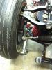
I have recently installed the Revington kit for bump steer on my TR3A and it looks as if your tie rods are not close enough to the disc. There is a picture, if you do a search under "vague steering" in theTR3 forum.
Regards,
Robert
-
It's been 21 years since I did my own and 6 years since I finished Franks. The bolts shown go through the holes in the floor pans, 2 near each "A" post and 2 more near the latch end of the doors. The extensions on the inner sills are just below the bottom side of the floor pans, then the rubber support pads sit on the out-riggers on the frame. The bolts go through the holes on the pads and these bolts are secured to nuts welded on the bottom of the out-riggers.
Edit - Corrections added.
Once you have done the above check that the floor sits on the small shelf of the inner sill. My inner sills were from Heritage and the brackets had to be removed and re -welded so that the floor was in the correct position wrt the sill.
Robert

Wiring harness TR2/TR3
in TR2/3/3A/3B Forum
Posted
It is my understanding that TR2 or TR3 came from the factory with a braided cloth covering on the wire harness. Late TR3A and TR3B came with vinyl clad wiring harness. It is possible that the wiring harness was produced by Standard Triumph in the 60's for replacing the wiring harness of a TR2 and TR3, therefore it is technically NOS, however not the same type of wiring harness the TR2 or TR3 left the factory with.