


Tony M
-
Content Count
14 -
Joined
-
Last visited
Content Type
Profiles
Forums
Calendar
Posts posted by Tony M
-
-
22 hours ago, Rob Y said:
I was talking with some guys at my local group yesterday and there was a feeling that changing the break calliper to a 2 pot (or is it 4 pot) was a better upgrade compared to changing the servo.
What are the opinions on this forum?
Maybe an easier mod, less modification required but only improves the front brakes.
I look forward to hearing your thoughts. I’m really interested in this servo mod, but I wouldn’t be able to do the machining if the spacer myself.
Cheers, Rob
Hi Rob. Last year I changed mine from original 2 pot to the BCC 4 pot with new drilled discs. Yes it did improve things but I still wanted more gain from the servo. I cant tell you what improvement this servo upgrade will give on standard brakes though. Front end upgrade was approx £800 and took me quite a while . This servo was easy in comparison and much cheaper.
-
12 hours ago, Z320 said:
Hi all,
also no problem here to lock all 4 brakes on my TR4A without a problem,
not like on a modern car but absolutely OK (I use a 0.625“ master, very pleased with this „booster“)
When I compared the brake pedal mechanism of my 4A and a TR6 I noticed
they had to make the leverage ratio much worse on the 6 to avoid overdoing with the servo.
This is why the TR6 brakes really bad with a not working servo.
This might be very simple knowledge but worth to point out?
Ciao, Marco
Hi Marco. I just wanted more bite without having to stamp on it. I have uprated the calipers on this 5 but it still needed a really heavy stamp. My ankles are not as strong as they once were and this has really made a reassuring improvement. I may look at lightening the clutch as well now. The remote servo shown previously in this thread is something that I may look into.
Regards
Tony
-
13 hours ago, harrytr5 said:
Hi Tony,
On the clevis pin end, I do not see a threaded rod or a nut welded onto the clevis pin bracket (or am I missing something) the link for the servo does not show a threaded end
clevis pin bracket.
Just love what you have done.
Regards Harry.
Hi Harry. Thanks. I agree that the picture shown on the advert doesn't show a threaded rod for the clevis pin clamp, but I ordered that and it came with the threaded end. At the point of ordering I didn't really consider that there might be a problem with the length or adjustment. I was looking for the part number 9157699 and took a chance.
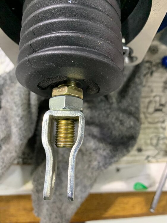
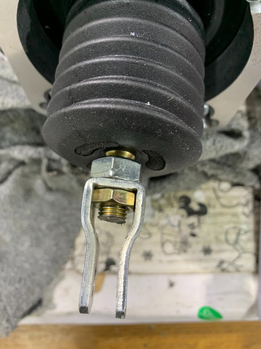
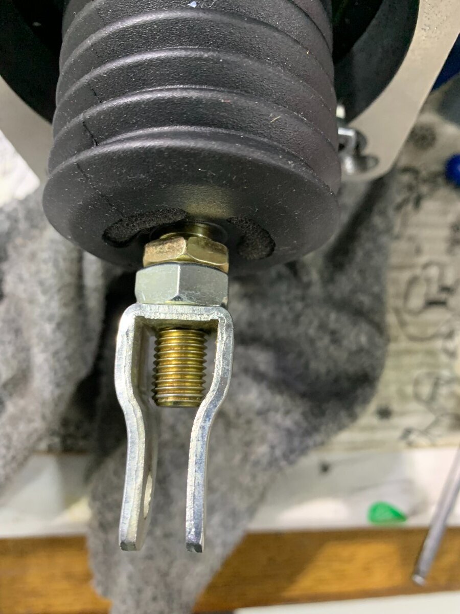
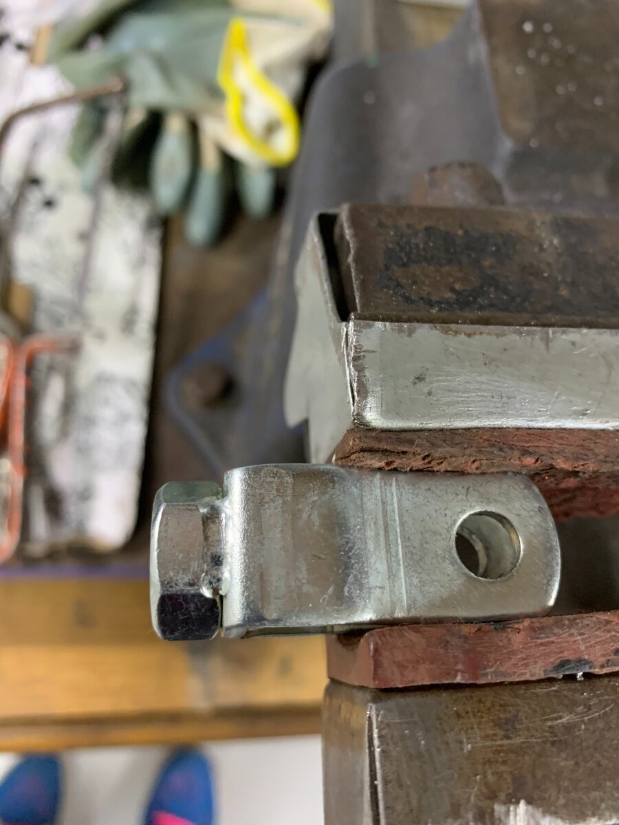
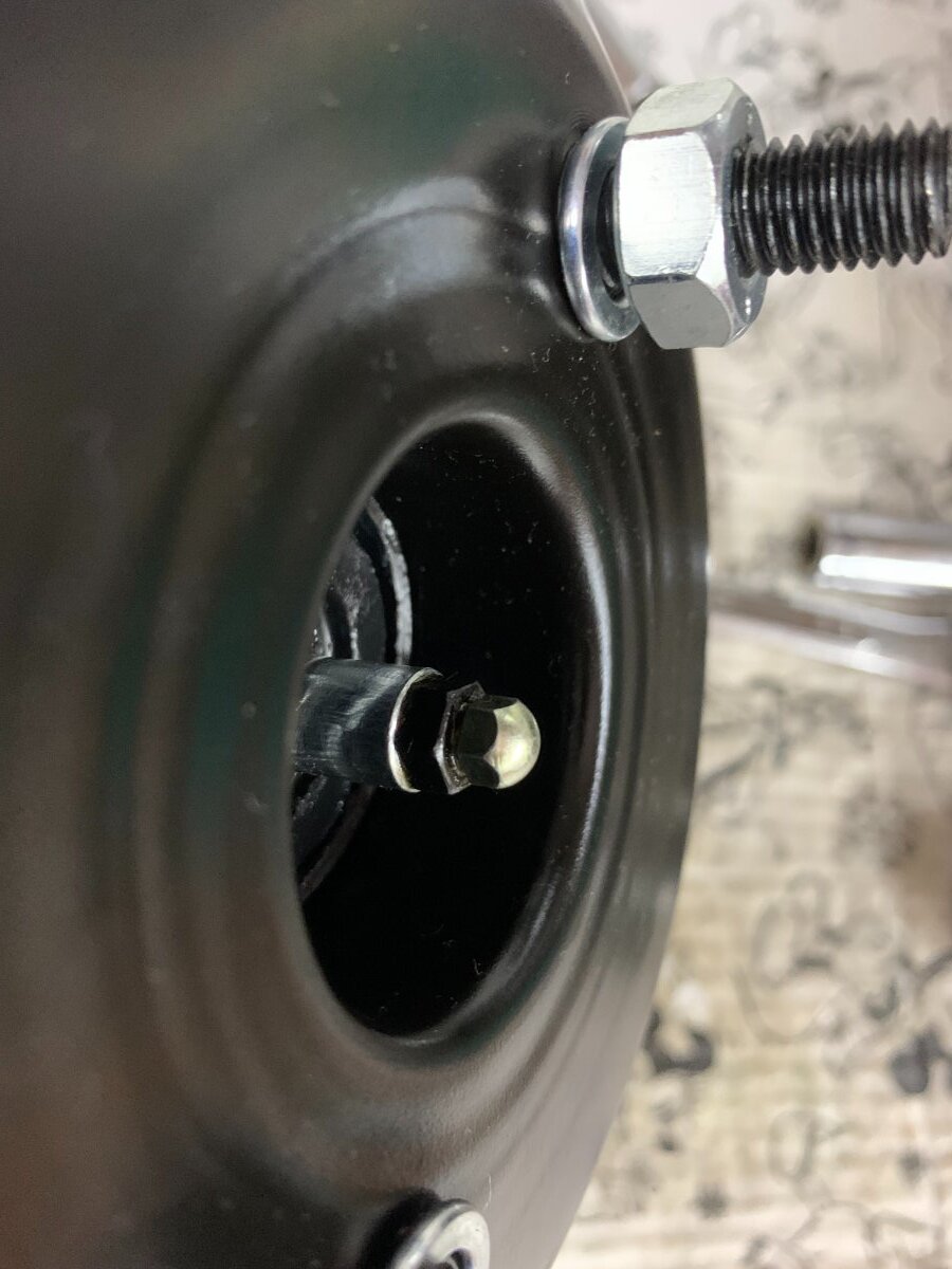
In the pictures I show a closeup of the clevis bracket held in the vice before I used a junior hacksaw to cut along the 2 welds that held the silver nut on. I then adjusted the thinner bronze lock nut by filing 2 edges, so that it would slide inside the bracket and the two nuts could then be set anywhere to alter the length and rotational position of the bracket. I had to shorten the shaft a bit to get the position I needed.
Regards
Tony


-
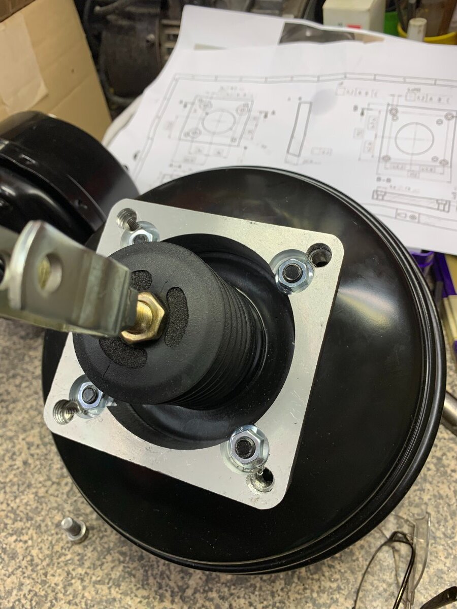
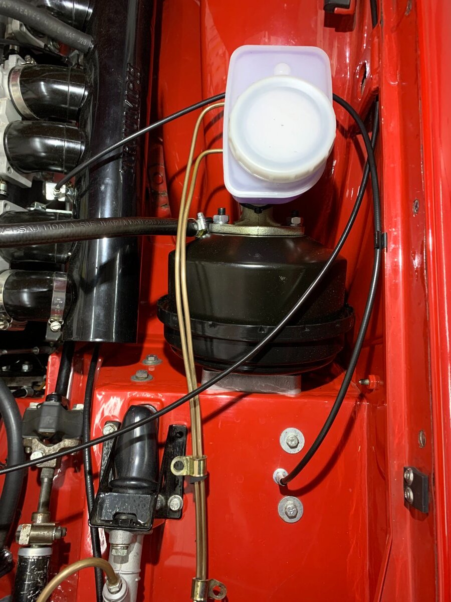
Having just completed my install I thought I would post the way I had completed the mod. First off the road test has proved what a brilliant upgrade this is. The brakes are now much more powerful. A real modern car touch.
Having looked carefully at the previous installs that used a new block of aluminium I thought that the original spacer would actually work.
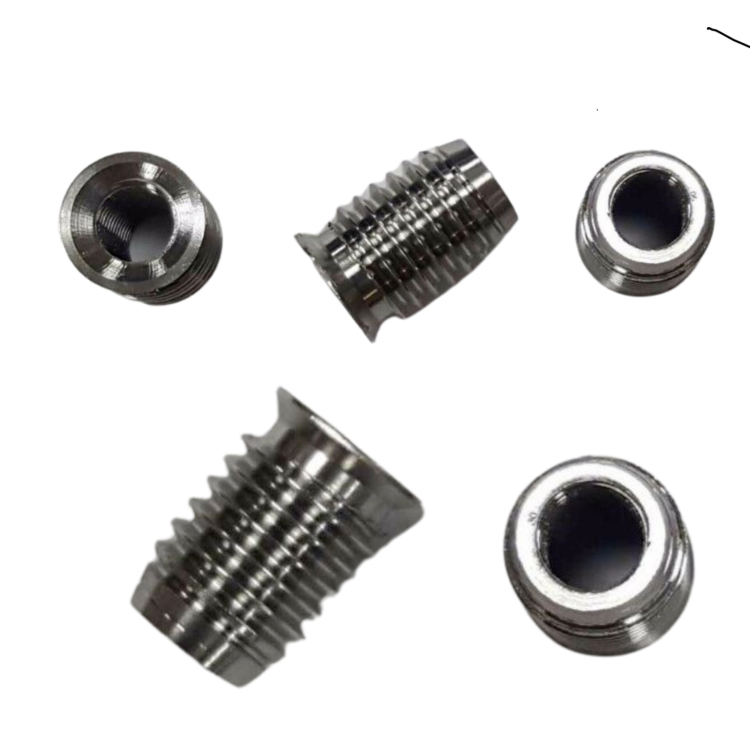
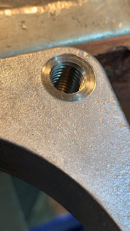
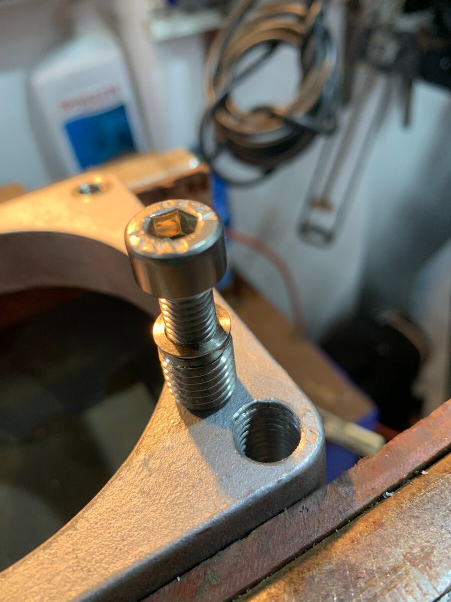
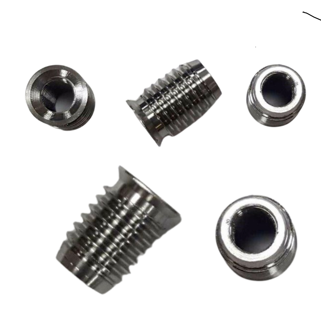
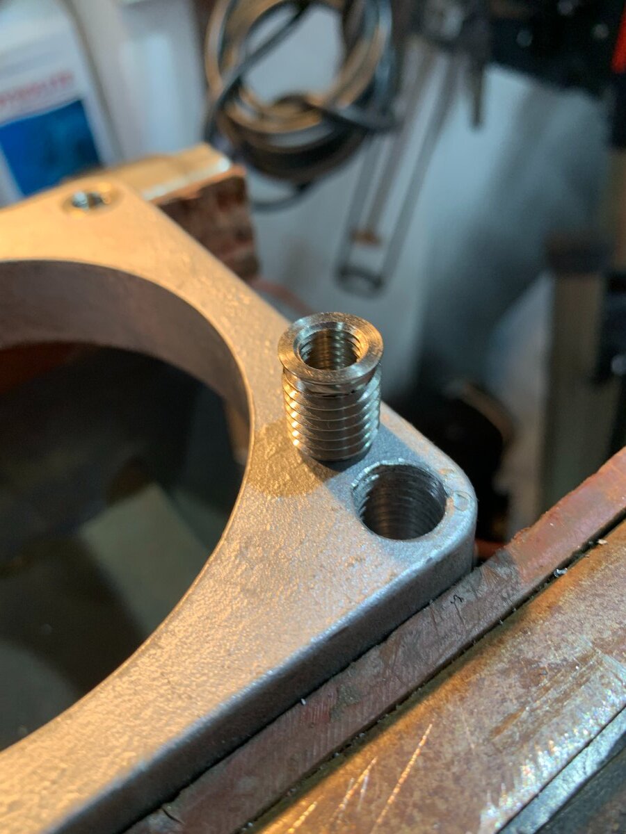
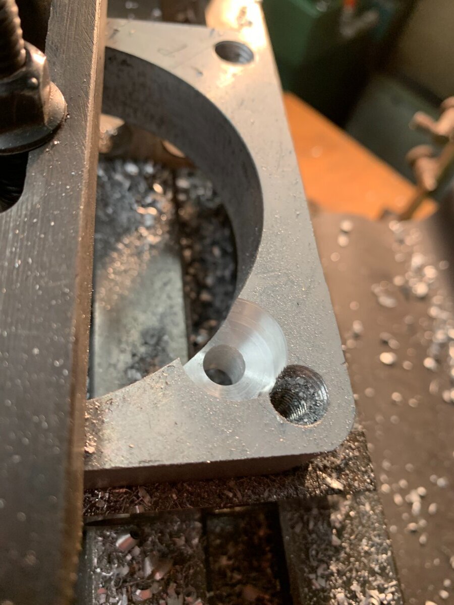
I drilled the existing spacer holes out to 10.2mm and tapped to 12mm. I purchased inserts that reduced from 12 to 8mm threads. I wound these in tight with an Allen bolt with a bit of oil on it, so that when reversed it would release from the insert easily. https://www.ebay.co.uk/itm/222455691053?var=522319792217
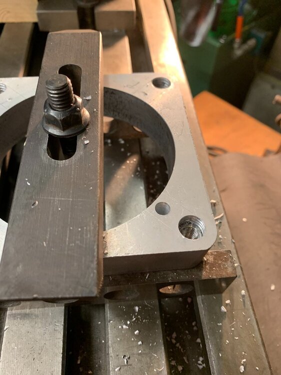
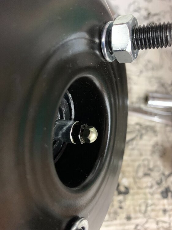
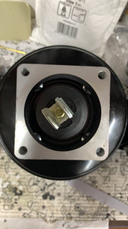
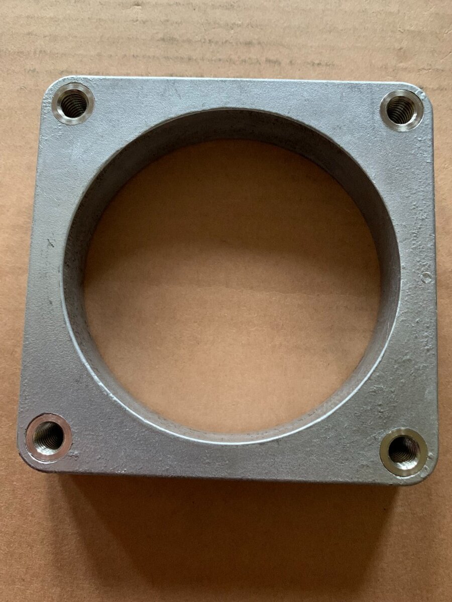
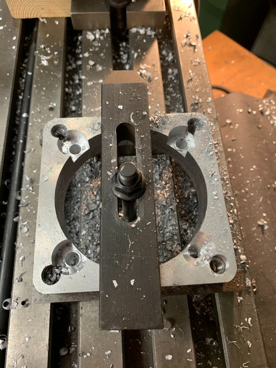
These fitted flush really nicely. The idea being to use Allen bolts from inside the car to secure the servo instead of fitting studs to the spacer. This made installation easier than the original servo! The spacer had to be marked accurately for the locations of the studs on the new servo. These are clearance holes. The spacer then needs to have recesses cut that would allow the nuts to be tightened by a slim line socket. This was achieved using a miller. It’s the only way to get a flat accurate hole (Many thanks to Neil from our local TR club for his help with this). As has been previously mentioned this spacer for right hand drive cars is made square and not offset. This installation meant that the inner wing did not need to be dented at all! It fits snugly but without any problem. The length of the clevis pin clamp needs to be modified as it will leave the pedal much higher than original. I cut the nut off and filed two edges down on the locknut so it would fit inside the bracket and allow it to be locked up. I had to cut the shaft shorter by half an inch or so. This allows a good range of height adjustment for the pedal. One thing to watch out for is the small doomed head that pushes into the master cylinder. I needed to reduce the length. I managed this by removing the threaded pin and locknut. I filed the locknut to half its thickness. I also had to file the dome down a small amount. This then gave me the original height compared to the original servo. Failure to set this height right will cause the brakes to bind on, so it’s worth spending the time to get it right. A quick tip is to have someone in the car to hold the brake pedal down to push the shaft out. I then wrapped insulation tape around the last inch of the shaft and held it with mole grips so it didn’t rotate when taking the central adjust pin out. The insulation tape reduces any damage and improves the grip. Finally the brake pipes will need to be remade to give a neat appearance. I might be fitting residual pressure valves to hopefully remove that first pedal push that gives longer travel. These are sold by various companies but are available from eBay at a much reduced price. This is the one I bought. https://classic-volvo.com/rem-bekrachtiger-oem-ref-9157699-91576991-volvo-onderdeel-35309772_b.html 120 euros including delivery to UK.


-
5 hours ago, FatJon said:
Collected the now adjusted car today. The required clearance is to have the pintle on the servo 16thou below the servo flange. The locknut was too thick so this was achieved by using a suitably sized washer and tightening the rod with some loctite on the adjustment thread. I suppose the same might be achieved with a thinner locknut but I wasn't there so I can't comment on that. All now working perfectly.
Great thanks for the feedback. My original servo has to be just below the front surface, as I did have a problem with the brakes binding after I adjusted it a bit too high, so I will look to repeat this position.
-
On 11/1/2021 at 9:27 AM, FatJon said:
A small addendum.
Don't forget to adjust the clearance between the servo actuator rod and the master cylinder piston or you will end up at the roadside with the brakes locked on. A big thanks to the chaps at Racestorations for the rescue!
Hi Jon. Yes I was just going to ask that! I have received my servo and offered it up but I did notice that the central pin is proud compared to the original. It does look as though it wont adjust in any more though. Did you adjust it?
Did you use allen bolts to mount the plate into the bulkhead? Many thanks for you posts.
Having just re read your post: .....
As a little update you don't need to "adjust" the bottom of the inner wing if you use bolts from inside the car to fix it rather than studs from the mounting plate and nuts inside. That occurred to me after I had finished, as the best ideas always do!
I think I will now try and bolt from inside as you suggest. It may be possible to helicoil the original block and mill out the 4 recesses to hold the servo nuts Ill get back about this and post a picture if it works. :-)
-
All great information. Thanks again. I have ordered the servo just looking for a supplier for the aluminium.
-
Hi Jon. Many thanks for such a helpful and detailed response. It has definitely inspired me to carry out this mod. Its surprising to see such variation in price for the servo! Did you keep the same thickness for the plate of 20.9 mm? I seem to be able to buy 20mm cut to size and hoped this would do. I'm going to remove my servo and check the mountings.
-
Great. Many thanks for the clear pictures. Have you road tested yet? Which part number servo did you get? Did you photograph the block before assembling?
-
Hi Thanks for that. And does it feel really light now and give good control?
-
On 9/11/2021 at 9:37 AM, stuart said:
Of course, a customer of mine needed a servo on his clutch due to loss of left leg strength.
Stuart.
I have a similar issue and would love to hear more about the clutch servo . I have been planning to use the Racterrations thrust bearing mod but a servo may be less hassle and cost.
-
Hi Lebro. Do you have any instructions for the operation of that particular timing light EQUUS 416677 ? I inherited one without any instructions and I cant find anything online. Many thanks
Sorry about the double post but I couldn't delete it.
-
Hi Lebro. Do you happen to have an image of the instructions for that particular timing light Equus 416677. I have inherited one but without any instructions and I cant find anything on line as its quite old. Many thanks
Regards
Tony


Volvo Servo Upgrade
in TR6 Forum
Posted
Hi Stuart. Do you happen to know what vehicle the remote servo is from. I hope to fit one.
Many thanks