


DSJ666
-
Content Count
12 -
Joined
-
Last visited
Content Type
Profiles
Forums
Calendar
Posts posted by DSJ666
-
-
Thanks, some very useful points there.
Floats etc. seem OK and choke mechanism is good.
I did change the needles and jets many years ago (from the Northern TR centre....so that dates them somewhat!). But probably done less than 20K miles since than as the car was laid up many years due to family commitments!
I have not had the jet assemblies apart, so I think that's the next thing to look at and I'll also check the needle shoulders.
-
Hi All,
I'm struggling to get the mixture correct on my 4A.
I can't seem to raise the jet high enough on the front carb, the adjusting nut bottoms out before the mixture is lean enough.
I did the basic starting setting at 1.25mm down from the bridge, but it was not possible to set it level with the bridge to start with. This setting is too rich.
Although I could with the rear carburettor and it is fine with plenty of adjustment up to the bridge and able to get the correct mixture.
It seems the front jet is too short! Is this possible?
Perhaps are AUD284 jets shorter? My carbs are AUD209's
Any ideas?
Thanks
-
Thanks Marco & TT, some good info there, although I'll need to try Google translate on the German!
-
Thanks Z320 for that diagram, do you have the key for the numbers? (I appreciate it'll probably be in German!)
Anyway, I've made a great leap forward!
Bob you are quite correct, the regulator contacts are the crux of the issue. I didn't realise that the cut-out relay function is dependent on the regulator even when they (allegedly!) closed and are not operating i.e. before the cut-out operates.
It would appear with mine that the regulator contacts when closed could not pass the correct field current to allow the generator to create the ~12.5V necessary to operate the cut-out relay. This makes total sense to me now as the function of the regulator is to control the field current and limit the output of the generator. Except in my case it was over limited due to pitting/oxide etc. so couldn't get past stage 1 (operating the cut-out)!
I worked all this out with the help of the Lucas Test Leaflet (linked above), so thanks to RobH for that. Bridging the regulator contacts with a screwdriver miraculously allowed the cut-out to operate!
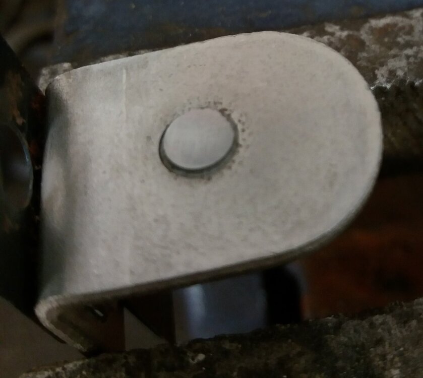
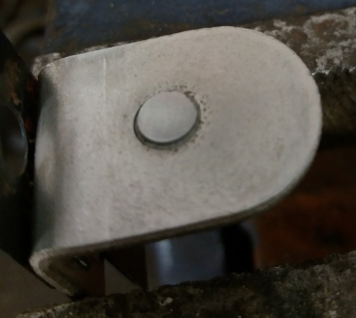
Having now established it was the regulator contacts I decided to bite the bullet and follow these very comprehensive repair instructions https://www.mgexp.com/phile/3/191288/REPAIRING_THE_STANDARD_RB106.pdf and refinish the contacts using a small dremel disc mounted in a pillar drill to ensure a flat and square surface. The contact surface was massively pitted to start with but ended up blemish free, see photo.
So after reassembly I'm now back in business, just need to spend a bit of time setting it up correctly as it seems a bit off the specified values. But I suppose its done alright for the last 50 odd years, just hope now it'll last a few more!
I think I'll also go the extra mile and as suggested in the repair instructions add a snubber diode across the field coil connection and earth to further preserve the contacts.
Thanks to all above for your assistance and the power of the forum!
Plus I've solved my lifelong mystery of figuring out how a control box actually works!

-
7 hours ago, Z320 said:
Did you plug the earth cable to the regulator?
If yes, what about the other end of the cable?
I'm not sure what you mean? The dynamo test is total independent of the regulator, just disconnect the F & D cables from it and do the link etc.
Or do you mean is there a bad earth to the regulator? If so, it seems good from a continuity test.
As RobH suggested, I'm now thinking its somehow related to the field current being reduced through the regulator and thus limiting the dynamo output voltage. I'm going to give some attention to the voltage regulator side of the control box.
I was previously focusing on the cut out relay as it was that which wasn't functioning but I now think that's a symptom and not the cause.
-
1 hour ago, RobH said:
If the dynamo isn't giving much voltage when on the car but tests ok on the bench, it is possible it isn't getting enough field current. I would start by checking the connection from the regulator F terminal to the small spade on the dynamo (yellow/green wire).
How did you test the dynamo independently? In case you don't have this, here is the Lucas test and adjustment instruction leaflet:
https://mgaguru.com/mgtech/books/pdf/Lucas_Generator_and_Control_Box_Tests.pdf
Thanks for the link...some really good info to absorb there!
I think I actually did what is stated on the instruction leaflet for in car dynamo testing. (Part 1 Test 4 Reading A)
I connected a short cable link between the field F cable from the dynamo with the D dynamo cable (both disconnected at the regulator end) then put my voltmeter between the link and earth. Started the engine and slowly increased the revs, it was giving increasing voltage up to ~20V.
So that seems OK so far and should mean the dynamo and F & D cables to the box are good.
I think I'll now work through the rest of the test leaflet and see what I can deduce.
Thanks very much for your input its spurred me on!
-
Hi all, I seem to have a weird situation I cant fathom so looking for a voltage regulator expert!
My voltage regulator wont operate the cut out solenoid.
I've tried two different voltage regulators (both tested the cut out independently with 12v supply and the cutout worked fine)
I have also tested the C40 dynamo independently and is giving out plenty of voltage but when connected to the voltage regulator it wont go past 7-8 volts which is too low to trip the cut out. (as needs roughly 12v)
So I'm not sure which way to go here as both elements seem good separately but not when connected!
Where is the voltage drop occurring I wonder!!!
Anyone any ideas?
Thanks
-
Hi All,
I have a issue with my ammeter needle flicking wildly all over the place.
It doesn't happen all the time and is often steady and reading correctly and I'm still trying to find some logic behind it's flicking, ie engine speed, electrical load etc.
I'm guessing it is a voltage regulator/control box issue although the battery stays charged so it must be working to some extent.
So just wondering if anyone has any tips as what might be the issue. (Its a RB106 voltage regulator on a TR4A)
Thanks.
-
Running repair...I was just checking the car over ready for a trip to the Silverstone Classic this weekend and noticed the aforementioned bolt missing!
Due to time I've done a stop gap temporary fix with a smaller bolt and nut and will replace with the correct one a.s.a.p. now I know what I need.
Cheers
-
Cheers Bob,
Yes that's the beasty...great!!
Problem solved.
-
Hi all,
Anyone know the bolt size/thread type for the dynamo tensioner strap on a TR4a. The one that goes into the engine, not the dynamo.
Cheers
SU HS6 Jet Height Adjustment
in TR4/4A Forum
Posted · Edited by DSJ666
Sorted!
Turned out the jet WAS too short!
Tried a cheeky fix which worked......I carefully removed the ferrule which then freed the jet from its plastic housing....reset the jet position and refitted the ferrule which secured the jet. (There is actually a small groove around the lower portion of the jet which seem to coincide with the correct length)
Don't know if it was always like this and I hadn't noticed or it had got pushed in sometime, although I can't think how as they are very tight in the plastic housing. I know they look old and are in age but not in usage!
Anyway a rather unusual situation sorted and all good now.
Thanks all for your comments.