


Mike Herlihy
-
Content Count
26 -
Joined
-
Last visited
Content Type
Profiles
Forums
Calendar
Posts posted by Mike Herlihy
-
-
Tim, was the block decked sufficiently to remove the recesses completely? If not then the CP type flat gasket fire rings may be leaking when the engine gets hot. The cooling system will then get pressurised and cause your issues. A CR stepped fire ring gasket can also hold the head off in this situation. It’s worth using ARP head studs if you haven’t already. We’ve had issues with customer supplied new head studs going plastic as the upper limit of 80 lb ft is reached. The quality can be dubious.
-
I fitted one of the cheaper screens a couple of years ago. I’ve fitted plenty in the past to various vehicles of a similar vintage by roping in with paracord. I had to reuse the original rubber (which was fine) as the one supplied with the screen was far too long to stretch comfortably around the glass and stay in place. All was fine except the lower right and left corners. The compound nature of the curve in this area just wasn’t quite right and the glass is very slightly proud of the frame contour. Nothing that a decent quantity of screen sealant couldn’t cope with and doesn’t leak but I think if I was doing it again I’d go for the better quality. Lesson learned as usual.
-
Richard. As standard the rear hub carrier is attached to the alloy trailing arm with 6 studs which are 5/16 in diameter and carry a UNF thread. Over the years successive removal and refitting of the 1/2 in nyloc nuts has a tendency to damage the thread tapped into the alloy. Many on these forums will comment on the result of these studs failing. Not a good experience. Repair of the alloy trailing arm threads can be achieved by hellcoil inserts. A better solution is to enlarge the threads to 3/8. A stepped stud is then needed that is 3/8 dia to screw into the suspension arm and 5/16 at the other end to pass through the hub carrier and receive the 1/2 in nuts. CCD do a kit to address this issue.
-
Fitted a set of CCD driveshafts to my TR6 last winter and also updated the trailing arms to the stepped stud arrangement. Very happy so far. Also fitted a set to a customer’s Stag which he reports to be very good.
-
Good news Peter.
I had my original steering rack overhauled this winter so had to do pretty much the same procedure.
Enjoy the summer in your six. -
Peter,
I was unable to download your images but that’s probably my finger trouble with media devices. In any case it sounds like you simply need to rotate the entire steering column through 90deg and then reattach the steering wheel. The best place to do this is where the column attaches to the steering rack. I wouldn’t suggest disturbing the flexible coupling assembly other than the pinch bolt.
Assuming it’s a PI car, remove the intake plenum assembly, the flexible trunking and the air filter housing. This will give you decent access to the column assembly. Remove all three pinch bolts. Put the steering wheel back on temporarily and get someone to hold it firmly forwards. There will be enough combined sliding clearance in both the joints (just), to tap the joint at the rack and the flexible coupling, rearwards along the shafts sufficiently for the lower one to drop off the pinion shaft of the rack. It will probably all be tight so you’ll need to progressively tap each joint rearwards to gradually move the whole column assembly towards the bulkhead. You can get extra rearwards motion by slackening the locking collar right at the bulkhead but it shouldn’t be necessary.
Remove the steering wheel. Make sure the wheels are straight ahead (!), rotate the top end of the column to the desired position then re-engage the lower joint onto the pinion spline at the steering rack by gently tapping everything forwards. When you refit the pinch bolts, you won’t get them back in unless the splined portion of the columns are approximately back in the same fore and aft position. There are annular rings machined in the rack pinion shaft and the end of the upper column. It’s important that the pinch bolts pass through these for obvious reasons. Once the steering wheel is back on if a test drive shows it’s slightly askew, then one spline either way at the top end inside the car to get the wheel straight will make little difference to the indicator cancelling action. Any more than that and it’s better to make the adjustments at the track rod ends but you shouldn’t need to.
Hope this helps.
Mike H.
-
Mark,
If the carburettors are Stromberg I had this problem with two newly rebuilt units on a Hillman Imp engine. The casings had been bead blasted to make everything look pristine. This process inadvertently exposed corrosion pitting on the machined part of the float bowl that passes over the jet assembly. No amount of new O rings and reassembly made any difference. Fortunately new float bowls were still available and this cured the problem. The carburettors were the smaller CD125 but the principle is the same on the larger ones.
Mike.
-
Gareth,
The pros and cons of the modern constant velocity conversion over the standard set up has been discussed extensively on these forums in recent years. If you search rear driveshaft conversions you'll find plenty of opinions! I went for it simply to future proof the car. This is my second TR6 and I've owned it for over 35 years (yes I'm getting on a bit!). It's part of the family and my eldest daughter has put her marker on it when I'm finished with it one way or the other!. Although I've replaced the u/js over the years I had play in both the rear wheel bearing carriers, play in the sliding splines and yet again play in the u/js. I work part time in the classic car trade and myself and my colleagues agreed that this conversion is a nice piece of engineering. No connection to CDD just a satisfied customer. I'm not an originality nut and am quite happy to make sensible upgrades providing the car looks period from the outside.
Mike
-
Have just completed this conversion yesterday. I can confirm that it's a straightforward DIY job. The only part of the operation that's a bit fiddly is due to the fact that the new driveshaft assembly minus the bearing carrier has to be fed in from behind the trailing arm. The diameter of the inner constant velocity joint is too large to pass through the opening in the casting. To be fair this is clearly stated in the instructions. It's no problem on the left side but the lever arm damper needs to be removed. On the right side the exhaust pipes prevent access and need to be removed. As Steve mentioned, if you are going to the expense of this conversion it's really worth upgrading the trailing arms to 3/8 UNC stepped studs. The kit and jig hire will give you everything you need including the correct drill bit and UNC taps. This can be done on the car but my trailing arms were removed anyway. Consequently it was then straightforward to fit the driveshafts loosely to the differential flanges and then feed the trailing arms over the driveshafts when bolting up the mounting bushes. With the resultant assembly at full drop the springs will go back in but be careful to support the trailing arm with a jack so as not to strain the driveshaft against the chassis leg. The only specialist bit of kit needed is a torque wrench that will cope with 210 lb/ft to tighten the outer securing nut.
-
Jim,
Not too difficult but only with the right tools (as ever). I've just done this job on my TR6 but the rear driveshafts, springs etc were off as I have been fitting stepped studs to the trailing arms prior to upgrading the back end. In my case access to the O/S inner face was fine using a 9/16 brake pipe spanner. I'm guessing your suspension is all still intact in which case ideally you need a 9/16 crows foot spanner, 3/8 or 1/4 drive depending on your tool kit. You can then work in from the side with an extension, reach behind and loosen the brake pipe nut and the half nut on the end of the flexible. Trouble is if the star washer and the accumulated corrosion are doing their job the support bracket will bend. No problem however. Simply cut the flexible off. You can then use a 9/16 deep reach socket with another extension to go over the pipe end to support the whole lot whilst you slacken off the two nuts on the inboard side with your crows foot. Once things are moving you can of course use the 9/16 socket to simply unscrew the pipe and hold the half nut with the crows foot.
Hope this helps.
All the best,
Mike
-
Agree with Stuart on this one. I've had my TR6 for 33 years and only replaced the rear box for the first time a couple of years ago after I holed it in a lumpy car park. I used a standard steel one that I had on the shelf that I bought on ebay for washers because everyone was after S/Steel ones at the time. Heaven alone knows how the standard steel pipe sections have lasted this long but the car sounds just right. Mind you I wouldn't like to try and remove the rest of the system!
-
Sorry Rich,
Just noted you mentioned the Velcro connection. Perhaps your channels are too rusted to use in which case I guess it won’t help. Worked fine for me though.
Mike. -
Richie,
Sorted this problem on my car simply and cheaply. If you google TR6 window channel replacement it will show you a link to the Danielson family TR refurbishment. You’ll find a comprehensive article on eliminating rattles from inside the door. As suggested I used the non hook half of a strip of Velcro and stuck these in to the original channels. Takes a bit of care and quite frankly I was sceptical but did this around 5 years ago and all good so far.
Mike. -
Mark,
You need to avoid drilling from the vinyl side as apart from your own caution at damaging the vinyl, the drill bit can also 'grab' at the foam sheeting behind and twist it into a lump.
Best bet is to use a small soldering iron with a fine pointed tip. Simply melt a small hole in the vinyl and foam beneath (takes a bit of nerve at first!) then drill on through the backing with your chosen drillbit.
Works just fine.
Mike
-
I’m sure this will have been covered before but can’t find anything relevant.
After 32 years ownership my original toughened windscreen succumbed to a stone today and shattered on the way back from a group meeting. Pity as I was enjoying probably the last of the warm Autumn sunshine. Managed to drive home gently and successfully extract all the bits after carefully sealing up all the likely orifices.
Looking at replacement laminated screens the prices vary wildly from not much at around £80 to quite a bit at around £225 or so. There is obviously a reason for this. Anyone out there have any views/experience of what’s available? I’m quite happy to fit a new one as I have all the tools and did the job before when replacing the rubber a few years ago. I also wonder if laminated screens are thicker than the toughened ones in which case my existing seal will likely be a struggle.
-
Kevin,
Yes those would be the correct wheel centres for a CP series car. The font on my later wheel centres looks the same. If you have to buy studs, wheel nuts etc you’ll need the plastic collars that clip over the wheel nuts. These apply gentle pressure on to the plastic centre springs preventing rattles. Many years ago now I bought a set of stainless steel wheelnuts from one of the regular suppliers. Once buffed up on the bench polisher they were indistinguishable from chrome and no splitting off of the plating when you apply a socket.
Very much personal but tend to agree with you. The Michelotti bodied cars look absolutely right with wires. The 6’s less so as the design is so much sharper. Spend some of my retired time these days helping at a chums Classic car business. He has a customer with an immaculate Stag but it has wires. Somehow I’m not sure..........!
Mike
-
Kevin,
As I understand it, very early TR6’s had quite a few carry over parts from the 5 including the dummy Rostyle hubcaps although I have to say that in 40 years of TR ownership I don’t ever recall seeing one.
The steel wheels on the CP series car which yours is, had black wheel centres and would have been 15” x 5.5 J wide. On the later post 73 CR series cars, the wheel centres were silver to match the rim colour. I believe that a change to 6J (6”) wide rims was also incorporated but without going out to the workshop to check mine (1974) I couldn’t say for sure. The size is stamped on the wheel rim
As the previous poster indicated, you will need to change the shorter wire wheel spinner securing studs for the longer ones required to receive the appropriate wheel nuts.
A very easy modification in either direction on TRs. Most other popular classics are far more involved. MGB for example has a different axle altogether.
Mike
-
Ok let’s see what others come up with. If it’s a loud noise from the specific area of the wheel then I would look at the half shaft assemblies. It’s extremely unlikely to be something drastic like the drive flange being loose on the stub axle. As you probably know these are extremely difficult to separate from the taper. It’s possible I suppose for the wheel rim nut tapers to wear so that the nuts aren't pulling the wheel down completely but never come across that. In 40 years of TR ownership with 4 types the only one that didn’t have rear end noises was a live axle 4! The others were all IRS cars.
-
Hello Craig,
Clonks from the rear are a pretty common affliction and unfortunately can come from various scources. Have you got wire wheels? Once the splines wear these will make a noise as the loading changes direction under acceleration and braking. With the spinner done up tight play won’t be detectable with the wheel off the ground. Another favourite is the differential mounting brackets on the chassis although by now most of these will have modified at some point. Play in the sliding splines of the standard fit driveshafts is another coupled with backlash in the diff and play in the u/j’s. No doubt others on our excellent forums will come up with suggestions. I could go on but my money’s on the wheel splines.
Mike
-
Bill,
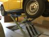
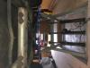
I wouldn't worry too much about the exact centre of gravity. If your scissor lift looks like mine in the thumbnails then the main headache is getting the car exactly central across the lift frame from side to side. Because the TR6 wheelbase is pretty narrow by modern standards if the car is too far forward or back even when perfectly centralised, the main frame of the lift will contact the inner edge of the tyres. As you can see I position the arms and pads under the rear trailing arms and front chassis rails. I frequently have the car on in either direction depending what I'm working on. It will be impossible to position the car in such a way that an excessive imbalance occurs and still be able to lift it. If your lift is different then disregard this drivel !
Having said all that, the lift has been a wonderfully useful bit of kit. Best thing I have bought in recent years. I sunk mine 6in into the floor so when not in use it's covered by scaffold boards and can be driven over. Clearly working underneath is not really practical other than at the front and rear overhangs (oil changes are easy for example) but just to raise the car a couple of feet to save the ageing back when doing simple underbonnet stuff is a great asset. One of those stools on wheels and the ability to raise the car three or four feet makes suspension and brake work a doddle. It's also great for polishing the sides if that's your thing!
Not sure why the second image is on its side. Clearly I'm a bit of an attachment virgin.
Hope you find it as useful as I have.
-
Just a precautionary tale really but would be interested to hear of other members experiences.
Around 8 years ago I purchased an exchange vanilla standard rear hub assembly (the supplier is immaterial as I doubt they refurbish them in house). To date that hub has done around 11,000 miles over those 8 years. An increasing droning noise from the rear whilst touring in France last year necessitated investigation during the winter layup. No play was evident in either rear hub and anyway it's difficult to determine which side is the culprit just by driving the thing. As the car has done in excess of 115,000 miles and I have owned it for 32 years it was a reasonable assumption that 'the other one' was original and was failing. Not so bad after 44 years. I duly removed the whole axle shaft assembly, separated the hub at the outer u/j so as to be able to mount the yoke in the vice and turn the bearing carrier unencumbered. All felt perfect. To be sure I repeated the exercise with the 11,000 mile overhauled hub which still looked pretty new. You've guessed it, it felt notchy and sounded rough.
Luckily I have a couple of unmolested original spares, mileage unknown, that I purchased from an ever helpful Alec Pringle a few years ago to be 'on the shelf just in case'. One of these has been pressed into service and all is quiet again.
The overhauled unit looked like it had been done competently. The usual giveaway is how well the lock tabs have been folded over and the state of the outer axle shaft thread where the puller/press has been applied and whether the drive flange is still straight.
I can only conclude that the quality of the bearings available nowadays is not what it was. Anyone else out there come across this? Would be interested to hear.
-
Steve. Looks like lots of ideas here but if you want another I have two serviceable units that have been on my shelf gathering dust since I went the Bosch route 20 years ago. Quite happy to let one go for a mutually acceptable sim. PM me if you want one.
Mike
-
Peter,
Enjoy the ride on the low horse!
No I didn't fill with diesel but take your point. I'm still convinced it was a condenser problem. As has been suggested, a failing unit can earth the points and cause cutting out. I think the fact that a simple replacement contactless unit has enabled us to run trouble free is too much of a coincidence. Back my 1980's motorsport days with the TR7 V8 we always used to say that 90% of fuel problems were ignition related!
Mike
-
As a footnote to this saga I thought it might be useful to others to mention the final outcome and resolution of this misfiring issue.
As the car ran perfectly on my 'spare' distributor baseplate/points/condenser assembly I came to the conclusion as Peter Cobbold had intonated, that it had to be ignition related rather than fuel. I put the original 'new' assembly back in and the car did ten miles then expired at the side of the road in exactly the same way. As I had plenty of serviceable points of various origins in the workshop, I replaced these along with the braided wire from the original worn out distributor. The few condensers I had lying around would have been suspect anyway otherwise they wouldn't be in the box of useless spares we all keep. I didn't want to introduce an unknown. The car ran fine for 10 miles then expired.
I came to the conclusion that it had to be the condenser even though it was a genuine Lucas item from the NOS distributor. I have since read elsewhere on these valuable forums that they can simply deteriorate on the shelf with age. I recall the days of my father's Zodiac expiring on the newly built M6 and the AA man saying misfiring under load is usually condenser. (He didn't salute, I'm not that old!)
With the French trip looming I bowed to technology and fitted a basic electronic module. Very simple of course but did require considerable adjustment of the timing. We returned yesterday via the Channel Islands having done 1200 miles and the TR ran faultlessly for the whole ten days and was a great conversation starter.
Having recently retired I now help out a pal from my motorsport days who mostly builds competition engines for classic motor sport. He came to the conclusion some time ago that although just about everything is available for popular classics such as our cars, MG, Lotus etc., the quality is often dubious.


Steamy dials!
in TR6 Forum
Posted
Richard, have a look at Smiths-Gauges.co.uk also known as The Gauge Shop. He is in Edenbridge, Kent. Only last week I visited him to collect all six instrument bezels which he stocks. He will correctly black anodise them FOC if they are for CR series cars. With the bezels he automatically supplies all the correct section o rings that fit between the dials and the dash. He also supplies sufficient quantities of circular section material in order to cut to the correct length, superglue together, and fit between the bezel and the glass. This replaces the original material that degrades into a brittle mess. I suspect that this is what you need.
A very helpful chap, he even found me a replacement second hand needle for my rev counter which i carelessly broke when dismantling.