


djp852795
-
Content Count
10 -
Joined
-
Last visited
Content Type
Profiles
Forums
Calendar
Posts posted by djp852795
-
-
-
-
Firstly cheers for feedback: mine is similar to your pic, grease monkey.
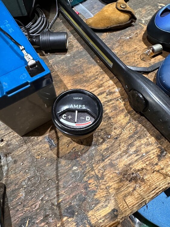
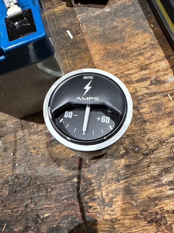
My old red/white ammeter doesn’t seem to work (no current when applied across posts) so I got a new replacement - and beefed it up to 60amp just in case taking on board “potential safety” issues. One had two blades. Tried to jerry rig a cross piece - to act as a double blade - onto the new one, but you can see how the plastic burned with the heat needed to solder the whole thing. (It has come off since as it fractured)
So now I have to decide whether to piggy back off the numbered ammeter or get the old red/white repaired - can’t be that difficult surely?! They’re simple enough aren’t they and I don’t really expect it to draw more than 30 amps - but more the shunt option.
Whilst I can probably get the numbered type to work using a form of piggy backing (not now worrying about smaller size connector) I would really preferred to keep the old red/black - but don’t want a massive repair bill. Think I’m talking myself round to repairing the original but temporarily installing the number one until it’s done. Any recommendations for a quality, reasonable specialist?
Really appreciate the feedback. It’s wierd that there isn’t a simple “heavy amp” piggy back connector produced by someone - I can’t be the only 6 who’ve had this “three into one” issue.
Derek

-
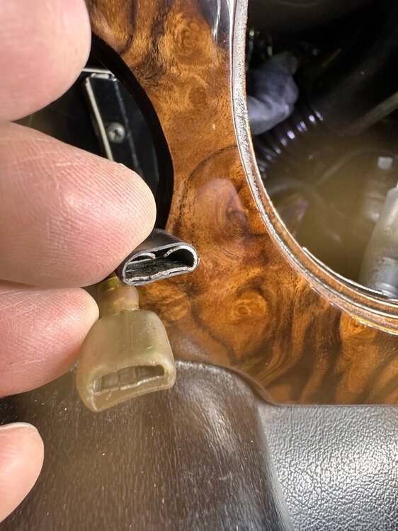
Thanks - the original “bolted” connectors look entirely different from the single blades coming through the back of the new ammeter - but I suppose I could try soldering one on an extra blade. Just seems strange that there isn’t a special heavy duty connector available for the purpose.
i did look for a piggyback connector but they all seemed so small/thin compared to the thick brown/white female 10mm wide connector on the wire at the moment - i thought they would restrict current too much. Rob, will the ones you linked be heavy duty enough for this then? If so,I’ll go that route.
Many thanksDerek
-
I am replacing my original ammeter with a new one but I find that there are only two ‘blades’ to connect to at the back - whereas there are four on the original -(Two brown and white off the same terminal)
Can I connect the two brown and white cables together ‘before’ they get to the new ammeter? - or rather how should I proceed connecting the wires as I can’t attach both the brown and white wires.
I’m conscious there is potentially a big current and I want to make sure all is well behind the dash before I put the Rev counter back.
Advice would be appreciated. Thanks.
-
Yes - the spade connectors do look ‘quite’ oxidised and the plastic covers have become brittle and darker (presume thru overheating?) So cut back and solder new spades onto good copper? And i guess I’ll keep checking for warmth as I’m really wary of the wiring melting.
Thanks Podone
Derek
-
Had to replace the rear section of the ignition switch after the connection became unreliable and the power to fuel pump became intermittent.
All now good, except connections at rear seem far warmer than I’d like. Might the cables be too small, or the connections themselves need to be better, ie cleaner?


Ammeter
in TR6 Forum
Posted
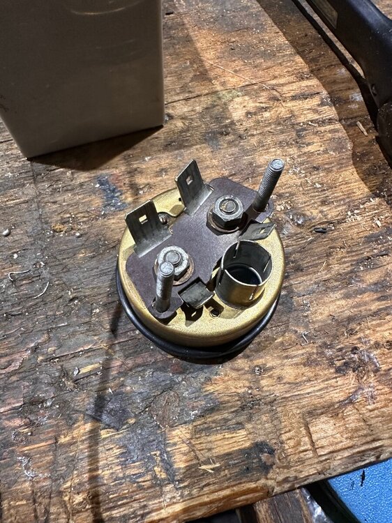
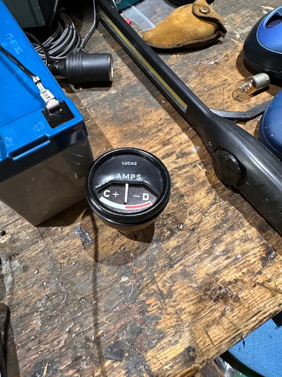
Close out for those interested: Located and opened the original non working ammeter to find that the 30amp wire behind the face had ‘blown’ (or rather “evaporated” - must have been a heck of a short). That’s why it didn’t work! I have been running round with a 60amp replacement for the last couple of years.
Because I preferred the original white red C/D face, I decided to replace the damaged 30amp wire loop in the original unit, with the 60amp ‘bar’ from the 60amp ammeter.
Behind the dial, I had to make sure that the ‘live’ bar was neatly placed behind the face, and clear of the pivoting indicator. It involved a lot of careful cutting, filing, and sanding to make it fit properly so nothing touched anything else.
I was super careful here, making sure that the inner terminals were bolted together really strongly, the insulator washers applied, and the blades cleaned off and the wires well insulated.
Turned ignition on ready to remove battery connector - but all good, and no need to play around with the original loom/connectors at all.
Thanks to all. Appreciate the feedback - esp RobH & Phil.