


NickR
-
Content Count
15 -
Joined
-
Last visited
Content Type
Profiles
Forums
Calendar
Posts posted by NickR
-
-
Hi,
I have never done it, but if you follow the link below it takes you to the "Six Tech" manuals one of which describes how you can get the hub apart, but it involves special tools also described in the download.
http://www.74tr6.com/6-tech.htm
Hope that this helps,
Nick
-
Hi,
Thank you for the suggestions. To answer Pete, no never parked.
I have now solved the parking problem with the help of the document in this link, which gives step by step instructions of how and what to test:
triumph.daveola.com/NOTES/Windshield%20Wiper%20Motors.pdf
It turned out to be no power on green wire, so I have cut the wire, and run a new one from the fuse box green.
I, of course now have a new problem! I was so pleased with myself that I put the wiper blades on and turned on the wipers to check the operation, but I had not noticed that the wiper park the wrong side. Instead of going left, they went right. Before I could realise what was going on and turn the wipers off, they turned beyond the bottom of the screen forcing the wiper arm into the scuttle, and pushing the wiper box back so that the plastic bit which holds the water jet broke. Then the fuse blew saving the car from further damage. At least the new motor seems to have plenty of torque.
I now have a gouge in the paint, and I have to buy some more plastic bits to go around the wiper spindles. Are these plastic bits all much of a muchness, or does anyone have any suggestions for where to buy them?
I am sure that I have seen somewhere on how to fiddle with the motor to get the wipers to park on the correct side (for the UK), but if anyone has the link to hand that would be helpful.
Nick
-
Hi
I should have said that I fitted a new wiper motor and rack as the wipers were slow anyway. Reading the forum about problems with worn racks etc I took advantage of a "special offer" discount from one of the suppliers and bought a new one. It could be that the new one has the same problem as the old one but I hope not.
Clearly I should have checked out the existing installation first. I know - a fool and his money ...
Thanks for your help
Nick
-
Bruce,
Thank you for the message. To answer your question, when I turn the wipers off they are off. They just stop wherever they happen to be when I turn them off (ie they do not park).
As I say, I cannot see any numbers on the switch at all, but if the terminals are numbered clockwise looking front on, then the wires are attached to the correct terminals according to your information.
Looking at the wiring diagram further, it seems to me that the problem is that I have no power on the green wire going to the motor, and that this should come directly from the fuse box, not via the switch. I have tried poking a wire into the green wire in the connector into the motor and then jumping it to the green on the fuse box, but that does not make the wipers park either. I am tempted to cut the green wire going into the wiper motor to get a good connection, but I don't really want to do so as it disappears into the loom and I would prefer not to damage the loom.
I will have to think about this a bit more.
Thanks,
Nick
-
Hi,
I have a 1973 TR6, with a two speed motor, and a round wiper switch.
I have a problem that my wipers are not parking. I have searched the forum and there are a number of similar threads, but they generally end saying connect wire A to terminal number x. Unfortunately, my wiper switch does not seem to have any numbers on it, so I cannot follow the instructions.
The wiper switch is round, and it has 6 terminals on it, 4 round the edge, and 2 in the middle. The switch has a raised "tab" at the top to stop it rotating, so looking from the front (ie the knob in front on me) wires are connected as follows:
10 O'Clock - Brown / Green
11 O'Clock - Red / green
TAB - 12 O'Clock
1 O'Clock - Green
2 O'Clock - Blue/Green
The 2 terminals in the middle of the back of switch are connected as follows:
Top one - Green / Black
Bottom one - Green (with a link to the green wire connected to the terminal at 1 O'Clock)
Looking at the postings, there is one which talks about turning the switch left for 1st Speed / centre off / right for 2nd speed.
That is not how my switch works. It is fully anti-clockwise for off, turn clockwise once for 1st speed, and clockwise again for 2nd speed (and then back again for 1st speed and off).
I used my multimeter to take some readings in the plug in the back of the motor, and this is what I found:
Switch off 1st speed 2nd speed
Blue /gr 0 volts 7 volts 10 v
Brown / gr 0 v 0 v 0 volts
Red / gr 0 v 10 volts 13 volts
Green 0v 0v 0v
Looking at the forum, it seems that the green wire should be live and it is not, so that is presumably why the wipers are not parking, but I do not know if the wiring at the switch is wrong, or if the green wire is broken / miss-connected somewhere (it just disappears into the loom).
I would be grateful for any help,
Many Thanks,
Nick
-
Stuart, Many thanks. I bought the seal, and, although not the cheapest seal in the world, it is a very simple fit so worth spending the money to save time and frustration (and probably failure to get the other one). Nick
-
Hi all,
I have bought a second hand GRP back light and surrey top, which I am trying to fit to my TR6. It came with lots of bits, and i am trying to assemble it before I fit it. At the moment, I am having trouble getting the seal between the backlight and the car to fit to the bottom of the backlight. It is quite difficult to push onto the GRP frame. One reason is that the GRP lip at the bottom is not a uniform thickness, and it is very difficult to push it one the thicker areas, and if I do, then it comes off. There was some evidence that a previous seal had been glued on with evostick type contact adhesive. Is this the right thing to do, or does it just push on. Given the time that it is taking me to push the seal on, I do not think that i would get round the whole perimeter before the glue had set.
Any advice will be received with thanks,
Nick
-
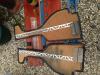
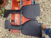
Hi,
I made a modification to my kidney pads as they were bending and falling out. I added an aluminium stiffener to the back of the pads to stop them bending so much (I used some aluminium angle that is used to finish off an exposed edge when tiling in a bathroom or whatever - readily available in a DIY store).
It is quite thin, so I was able to push one end under the metal angle bracket which clips onto the H frame, and then I used a couple of self tappers into spire clips to attach it, one in the middle and once at the other end.
You can see the heads of the self tappers, but as the pads are normally under the dashboard it is not easy to see them. If you were making your own or just recovering them, then you could make a neater job by using pop rivets with a washer either side to attach the stiffener before the cover material was added.
It stiffened up the pads so that they were quite a tight fit and had to be pushed in firmly. They now stay in place and do not bend.
There is also an added, unanticipated bonus that, as they are now straight, there is a much bigger gap between them and the gearbox tunnel side so that the hot(ish) air from the heater can now get through to the footwell and the heater is much more effective.
Nick
-
Hi, my 1974 TR6 is available at around that figure. Send me a PM and I will send details.
I would add a photo, but cannot work out how to do it.
1974 Red (originally Mimosa) TR6 with overdrive. Mileage 112,000 approx
Major rebuild in the mid 90’s, including respray, and Engine upgrade to 150 BHP, with Lumenition electronic ignition.
Large history file with receipts and old MOT’s. going back to the 1980’s
I am the 10th Owner. I have had the car for 2 ½ years.
There are no known accidents.
MOT runs until mid July 2015
Heritage certificate is in the file which says:
- Car/chassis number CR/6136-O
- Engine number CR004080-HE
- Body T.3286-CR
- Date built 24th May 1974 (so tax exempt this year??)
Work done includes:
- Interior
o Walnut dash
o Motalita wooden steering wheel
- New Bosch fuel pump, filter, etc
- Recent fuel injection unit
- Recent replacement differential
- Hi torque starter motor
- Poly bushes on the front suspension
- Poly bushes on rear suspension and Koni adjustable damper conversion
- Stainless Steel sports exhaust system
- Fuel tank removed and reinstalled with new gaskets, etc
- New improved clutch fork release set up with new shaft and pin, and new clutch
- New clutch hydraulics (new mater cylinder / slave cylinder / braided flexible hose / new copper pipe
-
Hi,
Very useful thread. I have just replaced the hoses and this bulkhead piece (as mine was very corroded and had sprung a leak). I see from that pictures are taken from major rebuilds with the dashboard out. Looking at the pictures the jubilee clip tightener of the top hose in particular is above the hose and points to the right. This was the same on my car when I came to do the job, but I did mine with everything in place, and just removed the "minimum" to get access. I could not get a screw driver onto the heads of some of the jubilee clips to remove the hose, so I had to cut them off. Fortunately, they were the old type with two wires so I could get a bolt cutter onto the wire and cut them off. When I put mine back, I have put the jubilee clips with the heads all pointing down so that i can get a screw driver / socket onto the head to do it up / undo it. Although it is presumably "wrong", can I suggest to anyone doing this, that they consider turning the hose clips so that access is available from below as it will make it much easier to get the hoses off if you ever need to do so.
Nick
-
Interesting, I had always been under the misapprehension that the mask was to prevent the paint getting into your mouth and lungs.
Now I see the professionals at work, I realise that it is to stop paint getting onto your chin!
great video,
Nick
-
Alec,
Thank you for the helpful input. As I say, I am just doing a simple calculation and do not know the basis of the MHP /1000 RPM and RPM / 10 MPH data in the brown book - perhaps there is some "correction" rather than a simple geometric calculation?
Of course my spreadsheet is in inches, and you are quoting mm, so doing the conversion (at 74% aspect ratio) my circumference of 77.29" is 1963 mm (so essentially the 1965 mm you quote), and my 15" wheel diameter is 381 mm ( essentially the same as the 380 mm bead seat that you quote). This is with an OD of 24.61" or 625 mm.
By my maths, you are right that an 80% aspect ratio gives an OD of 645 mm (or 25.39"), but this give a circumference of 79.74" or 2025 mm
I have add a column into my spreadsheet with an 80% aspect ratio (see highlighted column in the attached file).
Glad of any assistance to understand the correct way of doing the comparison,
Nick
PS I now cannot see how to add an attachment so cannot post the file that I have, so help with that first please!
-
I am afraid that this is yet another query about tyre size of a UK car!
I recently bought a TR6 which has 205 x 60 R15 tyres, which make the steering quite heavy particularly at low speeds and for parking. The car also has very little ground clearance at the back, which I initially thought was tyre related, but I now think is either lowered or just sagged springs.
However, this got me thinking about changing the tyres, so I looked at the various posts which are comparing various tyre sizes against what was originally fitted. Most say something like " when the cars were new tyres were just specified as a wheel diameter, and a width, without the apect ratio which is included now. The original tyres were specified as 165 R15, and had an aspect ratio of 80".
Looking on various websites, I came across a tyre comparator spreadsheet on an American site which I downloaded, and played with the various tyre sizes discussed in the various posts. Doing this, you can see how the new tyres compared with the diameter and the circumference of the basis tyre.
I also looked at the Repair Operation Manual (the thick brown book), and there is some data in there about the original tyre size, and the RPM / 10 MPH at various gear ratios and MPH / 1000 RPM at a couple of gear ratios. I put this data into the spreadsheet, with a tyre size of 165 x 80 x R15 as has been advised in the various posts, and I found that it did not give the correct results match the quoted RPM / 10 MPH in the Repair Operation Manual.
Thus, I played around with the tyre ratio, and found that I could only get a match on RPM / 10 MPH if the 165 R15 tyre had an aspect ratio of 74%. Consequently, it seems to me that the original tyre size on UK cars was 165 R15 x74, not x80 as has been quoted on many posts.
The analysis assumes that the type is circular, so does not take into account that the tyre obviously has a flat spot where the tyre is in contact with the ground, so would change the effective diameter of the tyre (depending on tyre pressure), which would affect the calculations, but also be virtually impossible to calculate. Does anyone know the bsasi of the MHP /1000 RPM and RPM / 10 MPH data in the brown book?
This obviously changes the "correct" tyre to fit to match the original equipment. From my analysis, the closest matches that I could find were 175 x 70 / 185 x 65 / 195 x 65 / 205 x 60 (all R15)
I have a spreadsheet but the site will not let me attach it, so I have attached a PDF of it as it is the best that I can do. I am happy to send it or attach it if someone can tell me how. I would welcome the comments from those who have more knowledge and experieice of this and can show me the error of my analysis!
Clearly, we are talking small differences, so it is an academic exercise to a certain extent, and it probably does not make much difference in many cases, and different people may prefer to have different tyres to give higher or lower cars, better acceleration, etc, etc. However, I would be interested to hear other people's views on my analysis.
-
Hi Davidw ( et al)
apologies for delay for delay, I have a misfire problem taking my attentions. ( I will joined another threat for that problem!)
Hopefully the photos will be useful, havent added a phto for sometime. As I said these are a bit snug but I am very happy with them and are very comfortable and look the part.
I hope these are of interested, cheers, John Mac.
SORRY, can't get pics to show, what am I doing wrong?. Got one up now will try to add more later.
Any help gratefully received.
John,
I am looking to fit some MGF seats to my TR6. I would be very interested to get more information on how you fitted them in. Could you provide more details, or take some pictures of what you did? Thanks, Nick


Wiper switch wiring / wipers not parking
in TR6 Forum
Posted
Roy,
Many thanks. My ramp is not detachable, but is part of the plastic cog. However, I have basically done what you said, and rotated the plastic cog 180 deg on the metal shaft, and the wipers now park on the correct side.
Just need to get eh new plastic bit, and can put the wipers on,
Thanks for all of the help and support,
Nick