In The Garage - april 2021
April 2021 Issue 13
Welcome to Issue 13 of In The Garage. We are always looking for content so please let us know what is going on in your garage especially if you are a new contributor.
In The Garage isn’t published at fixed intervals but rather when we have enough content to make a reasonable read. Contributions don’t need to be a novel about major project; simple hints and tips or a picture and a few words of explanation are welcome.
Andrew Willmott – TR3
Rear Anti Roll Bar and Shock Absorber Uprating
Handling improvements on the TR3 have been a long-term upgrade that the rear anti roll bar and shock absorber uprating should bring to a close.
The large front anti roll bar reduces roll a treat but takes the standard cars tendency to understeer up to unacceptable levels. The solution is to balance the handling with an adjustable rear anti roll bar. Revington TR supply a kit to match the front ARB already fitted but at a price beyond my budget so as usual the solution would comprise a lot of labour input and time spent sourcing parts from obscure online sellers.
A phone call to Revington TR revealed that they were prepared to sell me the bar at a reasonable £90 without all the linkage and brackets which seem to amount for the bulk of the cost. Mounting brackets that would be welded to the rear shock absorber mounts were folded from 2mm thick mild steel and fitted with hydraulic pipe clamps from a local fluid power supplier used to clamp the bar.
Sliding links that provide the adjustment were machined from aluminium bar using the Myford lathe to mill the slots and face the sides prior to drilling and reaming the holes on the pillar drill and finishing by hand.
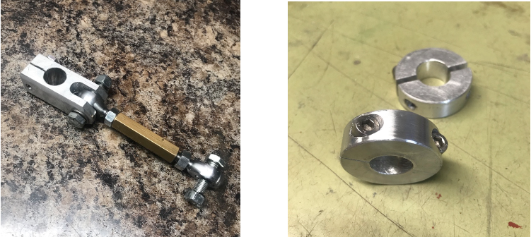
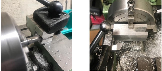 Rod ends were sourced on line from a specialist rally car supplier and the turnbuckle links were machined from a length of hexagonal brass rod found in my “lucky scrap box”. The brass is only 65% of the strength of mild steel but will still do the job and won’t rust.
As the spherical joints provide no lateral location for the bar a pair of collars and nylon bushes were machined to clamp around the bar adjacent to the clamps to prevent the bar from moving sideways.
After a trial installation the brackets were welded in place by my neighbour Mike Dove who I trust to produce a good weld on suspension and steering parts even when the chassis is a bit less than pristine and access is difficult.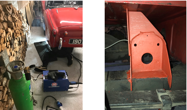
The final part of the puzzle was to mount the lower end of the drop-links to the axle. A simple modification to the outer pair of axle U-bolts was soon made by fabricating a pair of clevis plates for each side and having Mike weld them to the rear of the U-bolts close to the top of the spring.
With all the components ready and the welding completed the mountings were painted and the final assembly carried out.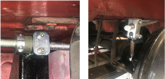
Uprating Armstrong Lever arm Dampers
While the dampers were on the bench I took the opportunity to refurbish them and uprate the valves.
I had two sets of lever arm dampers; one set that had been in use on the car since the mid 80s and a second eBay bargain set, which were allegedly refurbished. All four felt quite different when operated by hand when clamped in the vice and, one even had a different design of reservoir top cap fitted. I planned to strip them all down in the hope of making a good matched pair from the component parts.
Testing each unit using the same valve revealed the best body and piston assemblies so they were cleaned, flushed, and set aside while I sorted out the valve cartridges.
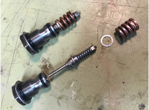
Stripping the cartridges revealed that I didn’t have two the same!! The cartridges provide three separate functions:
- Compression damping, varied by spacers under the compression spring.
- Rebound damping, controlled by an adjuster nut on the rebound spring.
- Low impact damping, controlled by a groove in the valve poppet allowing a restricted oil flow between thetwo sides at low speeds.
I had a poppet with a small groove, two with a medium groove and one with no groove at all. The springs and shims were variable too. So I stripped and cleaned all the component parts and by measuring them and close examination with a jewellers loop managed to assemble a matching pair.
Internet research revealed that racers ‘back in the day’ used to use a 0.080” shim under the compression spring and wound the rebound adjustment down to leave three threads exposed on the end of the rod. As these settings were suggested by track racers, and made a big difference to the spring preloads, I moderated my settings a bit and settled on two threads and a 0.060” spacer as my starting point for spirited road use. The adjusting nuts were soldered in place as Armstrong did from new to ensure that the settings don’t drift in use.
The dampers were re-assembled and filled with new motorcycle fork oil. Some advocate the use of higher viscosity oil but I consider that control functions can be adjusted in finer increments with thinner oil so stuck with the original specification SAE15.
The dampers were re fitted to the car with high tensile cap head screws, hi tensile nuts and specially made extra thick washers as I’ve had problems with them loosening off a number of times in the past.
The damper drop links had seen better days so a pair of turnbuckles was sourced online to replace them. Using a piece of S154 hexagon bar from my stock of scrounged scrap and offcuts a set of adaptors was turned up on the Myford lathe. One pair to connect to the tapered lever arm on the damper and the second pair for the bolted lower mounts on the spring pads.
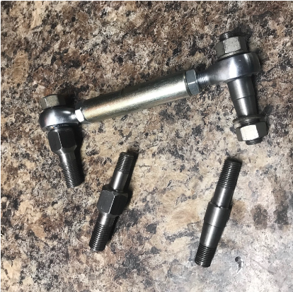
Fitting grease filled rubber boots over each of the four ball joints completed the assemblies. There was no room for such luxuries on the ARB links so it will be interesting to see how each set fares after some time exposed to the weather.
With the car back together a couple of adjustments were made prior to the first road test. The tyre pressures had previously been raised a few psi at the front to balance out some of the understeer so the pressures were re- adjusted to 26/28 and the rear ARB set to the softest setting as a starting point for the new set-up.
Initial impressions are good with neutral balance allowing initial understeer to be provoked into oversteer with the application of power and no sign of the previous snap oversteer in “hooligan mode”. Everything feels far more stable in long sweeping turns and through the quick roundabouts. The new damper settings soak up the big bumps while still providing a relatively good ride and seem to match the 161lb spring rate of the Revington rally springs well first time so there are no plans to revisit the damper settings any time soon.
I’ll be trying different settings over the coming year and it may be some time before I hit on the ideal compromise but it will be fun testing.
Further Damper News
While researching the damper upgrade I came across AJB Engineering who had made adjustable valves to fit our Armstrong dampers utilising disc valve technology as found inside dampers on modern cars. They were priced at only £60 and seemed like a great option. Until I found that they were made in limited batches and priced at £60 each plus VAT and post and packing. I shelved the idea but passed the information on to John Blake. True to form I received a single word reply 15 minutes later “Ordered”. We can look forward to a test report later this year.
Andrew W
Paul Gibson – TR6 Lockdown Refresh Completed
Well, all done after 4 months and after more money spent its plain to see the improvements isn’t it??
Doing this job has been like wetting yourself in pair of dark trousers, it gives you warm feeling but no-one notices!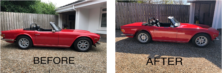
Paul is “hiding his light under a bushel” here. Having seen the finished job in the flesh I can confirm that real improvements have been made on an already outstanding car.
Andrew
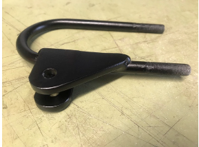
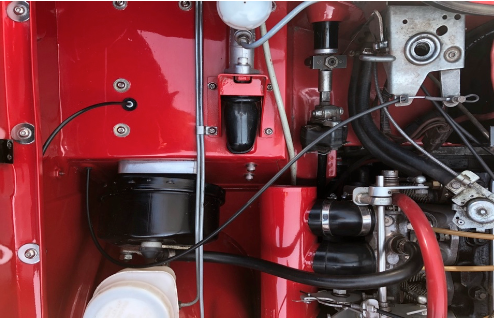
TR6 Bonnet Release
Refitting the bonnet is always a nervous time for me; will it open again?
I decided to try my standard pull as I habitually use the “emergency” release. It did function but I think Hercules would have only just managed to operate it. This is because it bends all across the engine bay and comprises a steel cable running in a spring-steel outer, the lever being on the passenger side.
Modification time. I used a Land Rover pull that features the same logo as the TR item (eBay £6). The steel cable runs in a nylon liner and was easily cut down to size. A small bracket fitted to one hole of the pedal box and only one hole drilled in the bulkhead for the cable to pass through in the corresponding position to the original, but on the driver’s side. The result is easy to find and use so no more fiddling around to locate the emergency release.
Scuttle Air Vent
As you know when TR6s changed from CP to CR the scuttle vent changed from a hinged steel flap to a fixed plastic grill. Having never liked the plastic item when I restored the car in 2014 I bought a metal vent lid but was unable to make it work properly because it required a hinge spot-welded inside the bulkhead that also holds the over-centre spring. Consequently I made a metal fixed vent.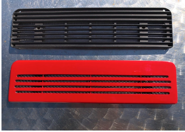
This time around I made up a cable-operated system using an old heater control. The scuttle flap originally only £17 is not available from the main suppliers and I’ve seen second hand ones go for £40 plus and I had already cut slots in mine doh!! So I made one from flat steel and welded on some stainless hinges all for a couple of quid. To make it’s operation less flexible I changed the outer cable for a solid tube (a bit of old car ariel) and added a stop so it doesn’t open too far. The control is fixed to the original bracket under the dash.
Chris Musselwhite
TR6 Lighting Improvements
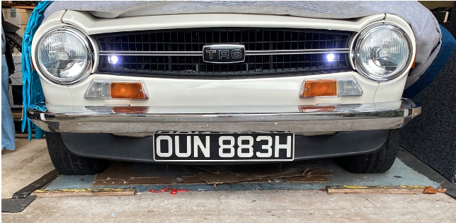
Chris has been busy during lockdown on a “see and be seen” project to upgrade the lighting on his TR6.
Discreet LED daylight running lights have been fitted in the grille and wired to conform to the current legislation requires in that they illuminate with the ignition circuit but switch off when headlights are switched on. An LED headlight conversion was fitted not only to improve illumination of the road ahead for night driving but also to give the wiring and switchgear an easier time due to the much lower current drain.
At the rear the reversing light bulb holders have been replaced with dual filament versions and fitted with white/red LED lamps. The white element functions as a reversing lamp while the red element is used both as a high intensity fog lamp and an additional pair of brake lights. The extra brake light feed is routed through a diode so that the original brake lights function as Triumph intended and doesn’t back feed and illuminate when the high intensity lights are in use. An additional high level brake light mounted on the roll bar and visible through the rear window of the hardtop completes the set-up and brings the lighting up to modern standards.

Tony Bunch – TR6
Expect the Unexpected!
After owning the car for 5 years I decided it was time for a “body makeover”. I removed all fittings, lights, windscreen and frame, etc and stripped the body back to bare metal. Off it went to the car restorers, and after 13 1⁄2 months was returned with 3 new wings, a new back deck and a lovely fresh spray job.
After refitting all parts I drove about 1 mile to the local garage to half fill the tank (which was nearly empty) with fresh petrol. About 100m after leaving the garage, the engine started to splutter and die. Repeated attempts to restart were unsuccessful and I noticed the Bosch fuel pump was unusually noisy.
After getting towed home, my first thought was had I filled the car with Diesel – but confirming this was not the case, my next thought was a blocked Bosch petrol filter. I removed and checked the petrol filter, but it appeared clean and no sign of contamination. As a further precaution, I drained the tank from the hose at the bottom of the tank – all the petrol was clean and less than 1 /2 teaspoon of tiny solids, and in addition, fitted a new fuel filter. Refilled the tank, confirmed pump was primed and attempted to start the engine. Pump still very noisy – checked injectors and an air/petrol mix was being pulsed out (but I am not familiar with how much should be sprayed on each pulse) – but engine still not starting.
Next thought – Bosch pump needed replacing Proceeded to do so (which involved purchasing the pump and yet another filter as one assembly), fitted same – but still a very noisy pump as before and engine not starting.
Next thought – for some reason pump was being starved or partially starved of petrol. Decided to drain the tank one more time from the hose at the bottom of the tank. However, this time tank would not drain! Tried to syphon the tank using a hose - but after about 10 seconds this also stopped! Looking through top of tank with torch – nothing obvious causing the problem.
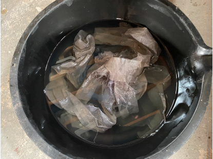
No alternative but remove the tank, whilst half full of petrol. The tank was eventually removed after skinning six knuckles and some extremely foul language! Tipped the tank upside down to drain the petrol and suddenly saw a wad of paper towel (almost translucent) trying to flow out! I removed the float sensor assembly from the tank and could now see paper towel and what appeared to be clear thin plastic tape floating around in the tank. Using BBQ tongs, I managed to recover all this debris, and confirm the tank was clean. The photo shows what was recovered! After refitting the tank, filling with fresh petrol, I am pleased to say the pump runs quietly, and after a few electrical tweaks the engine is now running as smooth as before!
The fact that this debris was floating around in the tank helps explain:
- Driving to the petrol station after car was returned was fine since debris was not blocking fuel feed hose.
- After first half filling the tank – the debris was stirred up in the tank, blocked the feed hose, causing theengine to stop 100yds later.
- I was able to drain the tank the first time because the debris did not block the tank feed to the pump.
- The tank failed to drain the second time because the petrol had been poured back into the tank and stirredup the debris – which then blocked the feed hose to the pump and also plugged the hose when attemptingto syphon out the petrol.
- Noisy pump was partial or complete fuel starvation depending on whether debris was blocking feed hose.So how did this debris get into the tank? When the car was collected on a trailer, I had made a large wad of blue paper towel and masking tape in the shape of a champagne cork and jammed it into the top of the tank - since the petrol cap had been removed. Sometime, whilst the car was at the restorer’s, that paper plug was either pushed into the tank (don’t think this is likely since I purposely made it such that it could not go in the tank) or the tank was left open and other paper and plastic strips were pushed or “fell” into the tank, during fitting of the new rear deck, or during spray painting? The restorer is an honest guy and genuinely has no idea how this happened although accepts it must have happened whilst the car was in his workshop.Lesson learned – never rule out the ridiculous, and just because a tank drains once it does not mean it will drain twice! Also, next time you fill TR, if wipe your hands with a paper towel make sure it goes in the waste bin provided!
Mark Radford – TR6
Mechanical to Electronic: TR6 rev counter conversion using a Jaguar 4.2 instrument as the donor.
My rev counter suffered from a major needle waver and on investigation I found that the spinning magnet was occasionally catching the metal disc, to which the needle is attached. This appeared to be caused by the drive cable pushing on the rev counter rear bearing and forcing the magnet forward as it rotated. I placed a paper spacer under the casing screws to provide more clearance for the magnet and found that the needle was steady but under read. This was because the induced pickup had been reduced. I tried to compensate for this by reducing the spring pressure on the needle by de-soldering the spring and moving it to its maximum position. This still did not resolve the problem.
I decided to convert to digital using a Jaguar 4.2 Rev Counter as the donor, which I found on eBay for £30. The Jaguar rev counter has a similar scale to the TR6 instrument as shown in the pictures, 180 degrees 1000 to 5000. The main issues are that the face screws are vertical whereas the TR6 ones are horizontal, and the needle shaft on the Jaguar unit is slightly thinner.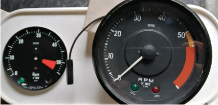
I found the conversion easier than expected. I made a cutout in the rear of the TR gauge housing and the plastic backing plate that carries the electrical connections was reduced in depth by 4mm. An additional earth was added to ensure a good connection. To compensate for the screw locations I made a simple adaptor plate. This also helped during calibration as shown in the pictures. To attach the TR6 needle onto a thinner shaft, I used a single strand of copper in the needle hole and pushed it onto the shaft.
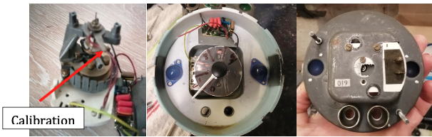
Calibration is very simple with the mechanism having an adjustable arm to increase or decrease the tension on the spring.
(TR6 geeks may have noticed that Mark’s rev counter features blue filters over the illuminating lamps, a feature only found on ’69 model year cars. Andrew)
Maintenance of TR6 Rear Lights
I had purchased LED replacement lamps for the rear lights and before fitting decided to complete a deep clean and improve the earths to each light holder. It is a common problem for these lamp holders to become intermittent because the earth is via the outer fingers of the lamp holder to the light cluster. To eliminate these poor connections I soldered separate earths to each lamp holder as shown.
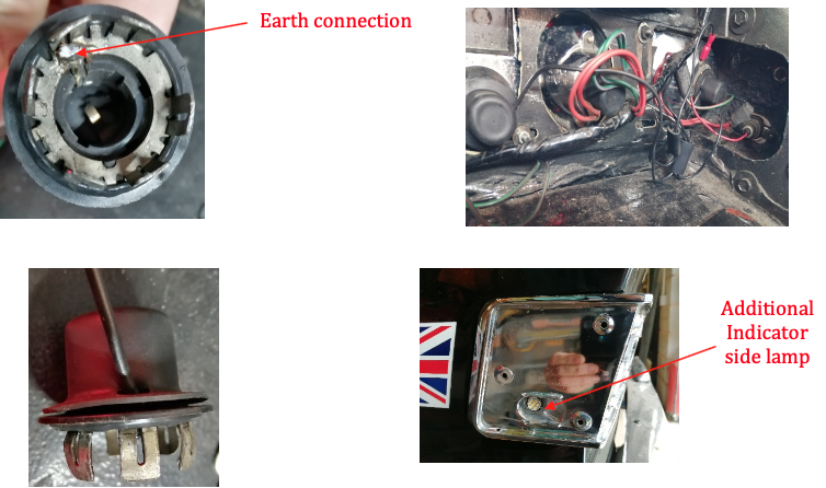
UK TR6s have an additional indicator lamp holes in the rear side clusters with no lamps fitted whereas lamps were fitted to American models as standard. The lamp holders are the same as the instrument lights for the speedometer and rev counter and are available as new spares. These were fitted as shown in the photo.
The later TR6s have an additional earth at the rear from the loom to the car body. This is not present on earlier models like mine, so a new connection to the body was made to reduce the load on the wiring loom.
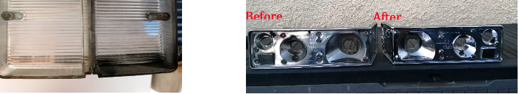
While the lights were dismantled I gave them a good clean and polished the reflectors, which greatly improved the brightness.
During the maintenance I noticed the reversing lights were dimmer than the indicators even though they were fitted with the same lamps. Investigation found that the reversing light switch on the gearbox selector had an impedance of 150 ohms when operated; it should be zero. I have an access panel on my gearbox tunnel and so was easily able to remove the switch and dismantle it to clean the contacts and cure the problem.

Mark
Exhaust Wrapping: A Race Engineer’s Viewpoint. From Bob Dove
I always enjoy reading Andrew’s ”In the Garage” which he e-mails to me and in the last issue I noticed a photo showing an exhaust manifold which had been wrapped prompting memories of my experiences with exhaust wrap on race cars.
As a race engineer in a previous life I was always ready to take on new ideas especially if they claimed increased performance; so when exhaust wrap came along of course I was one of the first to try it.
At the time I was preparing an Alfa Romeo Giulia TI Super for FIA historic racing in Europe so spent a happy afternoon wrapping the exhaust manifold with the appropriate material and tying it on with lots of stainless steel wire and wire-twisting pliers. Come the next weekend the boys took the car off to Monza. As I had recently started a family I did not attend meetings at that time and limited myself to car preparation for the team. All seemed to go well.
The next race Monza was Dijon with the long Mistral straight where the advanced aerodynamics of the Giulia (CD of 0. 34 in 1964) always gave an advantage over the two door Bertone Coupe Alfas.
By the end of the race that car was starting to sound like an old tractor and complaints were made to me. On return to my workshop I discovered that the exhaust manifold had cracked in two places where two pipes were welded together. I spent an unhappy couple of hours removing the manifold, stripping off the wrap, re welding the cracked joints and re-wrapping it before bolting it back onto the engine. Normal pre-race prep then continued. During the next race at Silverstone the same thing happened!
At this point I rang my exhaust man. Joe Ellis at BTB Exhaust in Woodford Halse near Daventry and asked him what I was doing wrong. Get that wrap off it was his answer. He explained that the wrap caused the temperature of the pipes to rise into a range where they metal became brittle and was unable to withstand the vibrations of a race engine running to 8000 rpm hence the cracking. “But I thought it was supposed to increase performance” I cried. “Not when the pipes are split “ was his answer. “If you want to keep things cool under the bonnet isolate what you want to keep cool”
At this point with only the generator to worry about on the exhaust side I bought some very expensive dimple finish stainless steel sheet and fabricated a cover for the alternator and dumped the wrapping in my dustbin never to be seen again.
A few years ago we fitted a Focus ST motor in a Mk1 Escort and the exhaust manifold ran very close to the starter motor. So close in fact that the starter had to be fitted upside down with the solenoid underneath but it was still very close. Again I found some stainless dimple sheet (Merlin Motorsport) and made up a cover for the starter motor which took me several hours and the loss of quite a bit of blood (that stuff is sharp!) Problem solved and when Andrew was looking to make a cover for his alternator a little while ago I still had enough left over for his job.
So I guess my message is that exhaust wrap isn’t all it is made out to be and in extreme circumstances can actually damage the exhaust. Manifolds on circumspectly driven road cars may look OK wrapped but surely a nice coat of Sperex looks smarter; as long as you resist the temptation to use white as it’s looks fade dramatically after a few weeks.
Bob Dove
Having read Bob’s article, which is sure to provoke some discussion, I was reminded of the time 30 years ago when I scrapped a relatively new mild steel manifold due to cracking and excessive rusting, although I didn’t connect it with the wrapping at the time. Google reveals lots of evidence in favour of Bob’s standpoint; much of it related to turbo cars with mild steel manifolds. I guess that most of us now use stainless manifolds and even spirited road use probably doesn’t heat things up to race levels.
Does anyone here have any direct experience of problems caused by wrapping on TR manifolds?
Something to bear in mind is the fact that on a TR the fuel system (be that carbs or injection) sits just above the manifold and exhaust wrapping makes an excellent wick for any escaped fuel.
Andrew
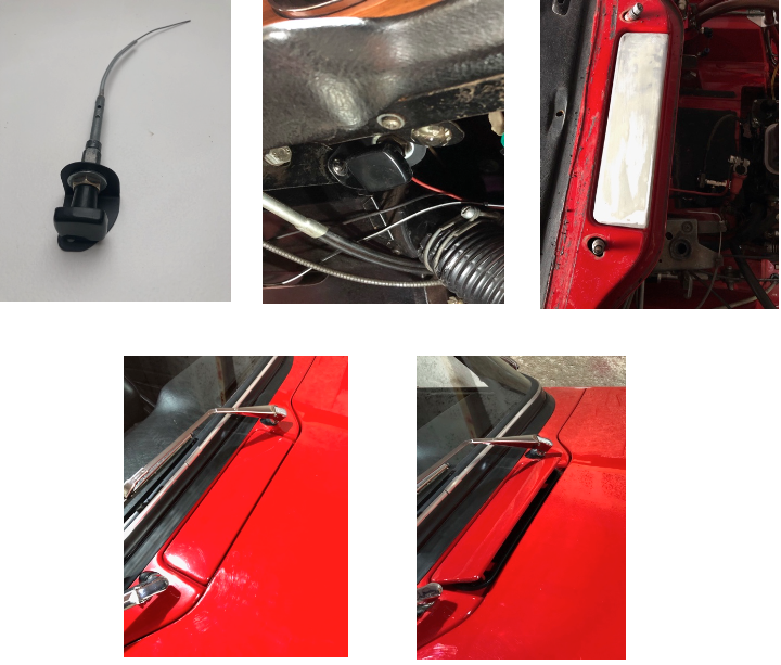
Andrew’s Parting Picture
For those as geeky as me here’s a picture of the original tool kit items, which I’ve been collecting for some years from autojumbles and eBay.
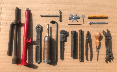
Andrew
You – Your Car
Thanks to all our contributors to this issue.
Contributions and feedback (positive or negative) are always welcome.
What’s happening in your garage?
Please make a few notes about your garage exploits and email them to me for the next issue. Contributions are best managed by sending in plain text with attached photos or in Word format.
Mail your notes and pictures to: andrewawillmott@gmail.com Andrew W