In the Garage - Winter 19
Winter 2019
Andrew Willmott – TR3
Front Suspension Geometry
I’d noticed that the TR3 top ball joints were getting a bit tired and thought that while I was working on
the suspension I might as well check it all through and improve things where I could.
The TR3 geometry was designed with the then current cross ply tyres and worm and peg steering in
mind and so in modern terms is compromised in a few areas.
i) Lack of Ackermann geometry.
ii) Lack of caster.
iii) Positive Camber (modern radial tyres perform best with a bit of negative camber).
I had already fitted Revington’s modified steering arms some time ago to address the lack of Ackerman
geometry and found they provided much improved steering especially the initial turn in.
I have had a set of 3 degree caster trunnions and the matching top wishbones from a TR4 in store for
some time and resolved to get them fitted together with some Superpro poly bushes and Revington
“red stripe” fast road/rally springs which had also been waiting in the wings.
That leaves the camber to address. The standard camber is 1 degree positive which is some way short
of the TR3 optimum of 1.75 degrees negative.
Revington TR designed an adjustable top fulcrum which has been used to good effect by many of their
customers and has since been copied by Bastuck and Moss but to my mind the design leaves a bit to
be desired.
The overly long mounting bolts are unsupported for most of their length and the fulcrum pin is notched
to clear the bolts
The top wishbones are set further apart than standard to allow for adjusting spacers each side of the
top ball joint making clearance around the fulcrum problematic. This adjustment isn’t required if the
original geometry is correct.
They have the additional complication of being adjustable so that they will suit any car whereas I only
need a solution correct for my car.
They cost quite a bit, they could do with a screw adjuster and they’re ugly.
On the positive side the Revington/Bastuck/Moss kit is fully adjustable allowing the camber to be set
exactly to requirements regardless of the original geometry of the chassis and doesn’t require any
personal poring over a CAD screen or drilling, tapping, sawing or filing in the workshop.
A solution advocated by some is to use shorter top wishbones. This will certainly provide the required
negative camber but doesn’t address the problem of the virtual roll centre being too low and will also
compromise the camber gain.
I sat down with a pencil, paper, dial calliper and Autocad to design an alternative and came up with a
simple set of spacer blocks made from bright mild steel stock bar. The blocks raise the fulcrum axis by
12mm bringing the virtual roll centre up closer to the front axle line rather than some way under the
road surface and feature a set of countersunk holes to attach to the original fulcrum mountings on the
top of the suspension turret and a second set of offset holes drilled and tapped to mount the fulcrums
further back on the turret. As the holes would overlap were they drilled to provide the required 2.75
degree change the offset is increased by an additional few millimetres. The fulcrums are then reversed
when fitted with the offset in the fulcrum bringing the pivot axis back to the required position.
Obvious…….well it is once you’ve thought of it.
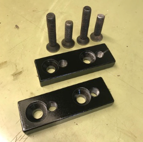
Camber blocks and fixing screws for one side
The minimum negative camber solid blocks can cater for is around minus 1.5 degrees as below this
value the mounting bolt-holes would clash. The blocks are manufactured for the specific angle and can
then be fine tuned by a slight slotting (a couple of millimetres in my case) of the top ball joint mounting
holes in the wishbones.

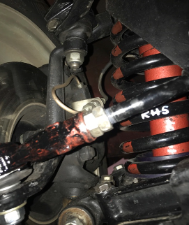
Offside turret with blocks fitted and Fulcrum reversed.
I intended welding the slots up and re-drilling the holes to suit once the fine tune had established a new
position but a neighbour who was a race engineer with a touring car team told me that they had done
the same with their race car and had run with slotted top ball joint mounts and never had one move.
Armed with the confidence of this information we completed a tour of the dreadful southern Irish roads
without the ball joints showing any sign of movement.
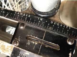
Camber set at -1.75 degrees
Revington’s 450 lb. Red Stripe road/rally springs were selected to match the existing Revington 161 lb.
rear springs. The stiffer front springs have stiffened the roll rate considerably and have proven to be an
excellent choice combining predictable handling with enough ground clearance to cope with rough
undulating roads. I was concerned that the ride qualities may suffer unduly but my fears proved
unfounded and long tours have proved comfortable and enjoyable.
The new geometry has improved the handling no end. The caster provided by the TR4 trunnions and
top wishbones has improved the straight-line stability and provided an element of return to centre
previously notable by its absence. The steering now loads up nicely on turn in.
The negative camber has certainly improved front end grip when in “hooligan mode” although the
steering is now notably heavier, especially when manoeuvring at low speed. The heavy steering
prompted the next project: rack and pinion steering.
Rack and Pinion Conversion
I’ve been tempted by a rack and pinion conversion for some time but the increasing wear in the
standard worm and peg together with the aforementioned heavy steering spurred me to action.
I’d done a lot of research over the years and rejected all but one of the commercial offerings due to
unresolved designs, increased turning circle or the failure to address bump steer. The remaining
contender was rejected due to excessive cost.
The best conversion uses a specially made rack based on a modified TR7 unit, as did a homebrewed
conversion I found detailed online. The TR7 rack features inner ball joints spaced only 6mm further
apart than the standard TR3 system together with an input shaft placed in a position broadly replicating
the original steering box axis so that formed the basis of my conversion. The TR7 being wider than a
TR3 requires longer inner tie-rods that would require shortening to suit the TR3. Because of this I
needed to source an original rack that could be stripped down for modification: new racks are not
easily disassembled and are essentially throw away items. An online action bid soon saw me the
owner of a reconditioned rack won for a bargain £29!!
The tie rods were soon removed and a bit of measuring and calculating gave me new dimensions
required for the shortened units.
One problem was that the TR7 tie rod threads were M14 and rolled onto the rod which was too small in
diameter to allow an M14 thread to be recut after shortening (rolling ‘grows’ the diameter as the thread
is rolled). Measuring the rod revealed that there was just enough material to cut a ½” UNF thread; the
same thread as a Triumph Spitfire track rod end which features the same taper as a TR3 steering arm.
The conversion could remain imperial and all Triumph.
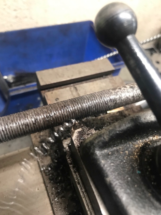
The track rods were a bit corroded and not quite straight, so rather than just cutting a new thread with
a die and risking it ‘running out’ the rods were mounted on my trusty Myford lathe with a dial indicator
and straightened with a big lever. They were then screw cut a few thou oversize prior to being cut
down to the required length and given a final run down to size with a split die. The rack was then
reassembled ready for fitting.

Straightening the tie rods
Screw-cutting the new thread
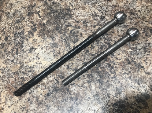
Original and modified tie rods compared
Brackets were to be welded to the chassis as any suitable mounting points were too far from the
required rack position and would introduce too much flex: not something you want in a steering
system. Brackets were mocked up with cardboard templates and fabricated from 2mm steel sheet. The
brackets were made 5mm lower than the calculated height in order to allow spacers to be added to
correct bump steer after fitting. Any similarity to commercially available brackets is entirely deliberate:
re-inventing the wheel is a waste of effort.
A TR7 lower steering column was found at the IWE Auto-jumble for a bargain £8 and eBay provided
the new Spitfire track rod ends. A new TR7 upper steering knuckle completed the kit and proved to be
the most expensive part at just under £50 including P+P.
A morning’s work saw the TR3’s nose and radiator removed and the original steering gear consigned
to a pile in the corner. I noticed that the original parts were unexpectedly heavy so the conversion
would save a bit of weight as a bonus. The brackets were ‘massaged’ a bit to better fit the chassis and
with them temporarily clamped in place the kit was assembled to the car.
The springs and dampers were then removed, the tracking set and the chassis lowered to its normal
ride height to check the bump steer. A laser pointer was mounted on a magnetic stand and fixed to the
brake disk. With the laser illuminating the target 2.8 metres in front of the hub 5mm of sideways
movement equates to about 0.1 degrees of steering movement making the setup more than accurate
enough. The suspension was raised and lowered through its normal arc of operation with a trolley jack
and the laser track traced onto the target. The first trace was miles out and I envisaged a rethink and
redesign of the brackets but a 5mm spacer made a huge improvement and another 2mm spacer
brought it in to a straight line over the normal range of travel. I was astounded at how much difference
even fractions of a millimetre made!
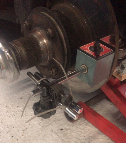
The laser pointer mounted on the brake disk
(Prevented from rotating by a large G-clamp
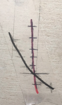
First bump trace improved with 5mm spacer (RHS)

With the bracket positions now confirmed a neighbour was called in to weld the brackets to the
chassis. He works as a fabricator welder on 4x4 conversions and modifies Skyline suspensions for
drifting so I opted for the confidence that his experience would bring rather than worry about my own
welding every time I drove the car. An hour welding and checking as we went saw the point of no
return passed; this TR3 will be rack and pinion forever now.
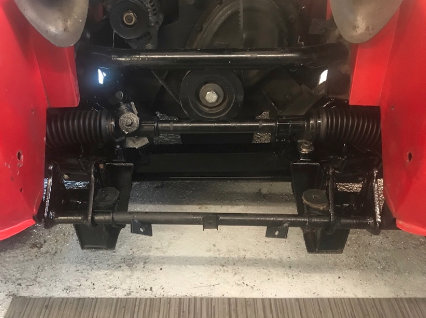
The whole lot was painted and reassembled before the bump steer was checked again. Nothing had
changed during welding so the new column assembly was fitted just requiring the steering wheel and
outer column be moved towards the driver by about 10mm. Springs and dampers were re-fitted and
the rest of the front end re-assembled. The car was lowered onto its wheels and the tracking checked
again prior to the first test drive.
First impressions were a revelation. The effort required to manoeuvre the car at parking speeds is
hugely reduced. On a straight and level road any small steering input is immediately felt as the car
responds to the wheel. When turning into a roundabout the driver can now feel the steering load up as
the lock is applied and the transition to exit the roundabout is smooth and progressive. I’m now looking
forward to some longer runs without the suspension shortcomings I’ve learned to compensate for over
the last 40 years. A bonus is the fact that the steering column is now partly collapsible. It’s nice not to
have the original solid column stretching out like a spear from the front of the car and aimed at my
chest.
Workshop Tip:
When I have access to the track rods I fit two half nuts to lock the track rod end. That way the inner
can be loosened a few turns and the second nut then locked against it. The tracking can then be
adjusted with a spanner on the nuts rather than butchering the track rod with a Stilson or Molegrip.
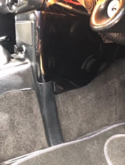
Vent Lid Seal:
Vent lid seals have been problematic for a number of years. The replacements are manufactured
from a dubious material which doesn’t last long and the moulding leaves a lot to be desired
requiring a lot of cutting and trimming to make them fit so that the vent lid will close flush to the
scuttle and bonnet.
I borrowed one from my local TR parts stockist (John Blake) and gave up with it pretty quickly. A
rummage through my garage found a length of 7mm o/d 3mm i/d silicone vacuum hose that
looked like it may do the job.
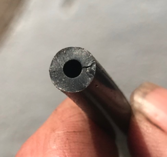
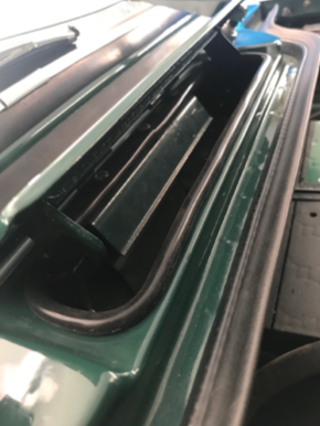
The tube was carefully split along one side and slipped over the lip of the air inlet. Closing the lid
revealed a perfect fit that doesn’t even require any additional securing to hold it in place.
John Blake – TR4 x 2
John writes:
Well, so much has happened since the last report it’s hard to know what to cover
My green car already had the drive train sorted but the bodywork was always….well, I liked to call it
patina, but I think others more accurately called it rusty crap.
After one of the front wings came lose at the bottom & started waving at other road users, I thought I’d
better sort it out before I lost it altogether & ended up with a lawsuit, so it was duly removed for a closer
inspection. In hindsight I almost wish I hadn’t as that became the start of a full body-off restoration that
has taken two years and has now seen the majority of the body panels replaced.
It has been an interesting excursion into the world of old body bodges & previous owners work.
I knew that overall maintenance fell short from the outset when I first bought the car as I had to sort out
the exhaust which I found was joined together in front of the crucifix with a baked bean tin & couple of
jubilee clips, I wasn’t too worried as I remember doing something similar myself but that was about 40
years ago when I couldn’t afford a new one.
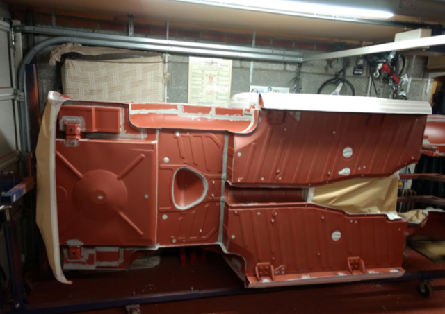
But that didn’t really prepare me for what I found on the bodywork. The floor pan on the nearside
consisted of four layers of metal, two plates on top of the original rusted out floor pan (covering the
body mounting bolts) and a further plate underneath which had been lavishly covered in bitumen.
The plates turned out to be of 3” profile galvanised roofing sheet that had been hammered flat….nice.
On both sides the sills were non-existent at the front & back.
On the plus side the front nearside wing was never going to come lose & flap like it’s mate the other
side as someone had had the foresight to actually weld it to the inner wing & baffle plate!
I was fairly soon to realise that a previous owner had adopted a policy whereby rust was never
removed it was simply knocked in hard with a hammer & then covered with anything to hand, if I was
really lucky that involved some kind of metal with a few tack welds or the occasional brazed joint and
on other occasions it was corrugated cardboard and a tub of body filler.
Here are a few examples of what I found:
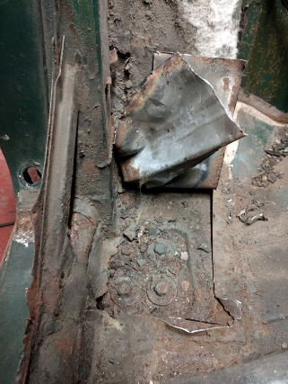
Front offside sill – or more accurately a picture of where it should have been; explains why the wing
was flapping at the bottom – nothing to attach it to.

Spot the body mounting bolts….aha, there they are under two layers of wrinkly tin
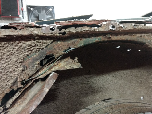
Rear offside inner wing – the dull red you can see at the top is plastic filler that I found in excess of 1”
deep in places…and more wrinkly tin.
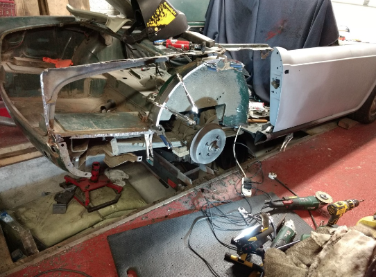
I did as much of the main bodywork as possible with the body still on the chassis, it was so bad that if I
had tried to lift it beforehand it would have fallen apart and I would have lost all the remaining datums. I
tried to keep as much original bodywork as possible as I soon came to realise that the new
replacement panels are at best a starting point for something useable.
To be honest the quality of the new replacement stuff was sole destroying on occasions, and I resorted
to seeking out NOS Stanpart or second hand used. When all else failed I made the panels myself.
The car was so bad that I have replaced all four outer wings, all four inner wings, one rear wheel arch,
both inner & outer sills, both floor pans, the boot pan, boot lid, bonnet & both doors, the bottom of both
A posts & B posts (I did buy new but they were so bad I made repair panels instead)………sounding a
bit like ‘Triggers broom’ by now?
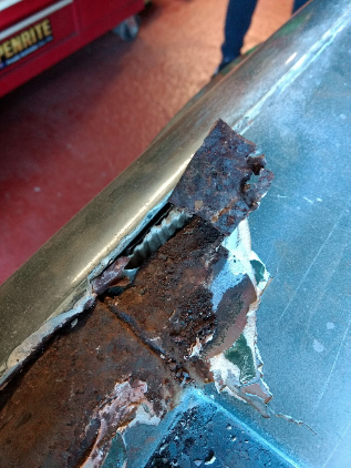
This time it’s ‘spot the corrugated cardboard’ on the rear nearside top deck where the rear wing
attaches.
Anyway – fast forward to the last few months which will save you from several hundred phots of me
sweeping my car up off the garage floor:
Body off and chassis strengthened & shot blasted and powder coated by a very dirty young lady……
I mean always covered in dirt….c’mon stay with the programme fellas…..
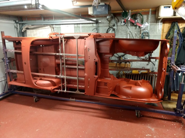
Chassis was in quite a contrast to the body – remarkably good, straight rust free condition – probably
in part due to the excessive amount of oil leeks this thing has suffered over the years. Freshly back
from powder coating:

Next up is possibly the best birthday present ever – a gift from my family for my 60th a hydraulic
rotisserie that has been outstandingly good. I confess I did make a substantial jig which was specific to
my own needs on this car but I’d never attempt a full bodywork job without this piece of kit – it just
made everything so much easier to do – finish all the welding underneath, replace the boot floor – it
has been brilliant.
The underside was then seam sealed & treated to several litres of stone chip followed by several
topcoats of the original Triumph conifer green.

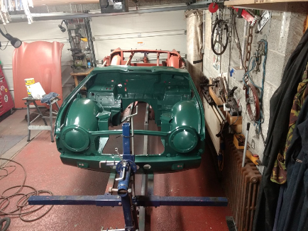
I was also able to prep & paint the engine bay at this stage
I needed to get the body off the rotisserie at this point to finish the inside the tub which was not
possible with my over–engineered jig in place.
Body sat back on chassis (temporarily only)
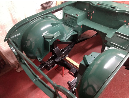
And the back end as it sits at present after the fire wall was fitted this week & a few alterations made
for the roll bar – pretty much ready to top coat the rest of the tub

I have also during this time rebuilt a spare back axle with a 4.55:1 ratio for sprinting and am I currently
building a 28% reduction ‘A’ type overdrive unit from a Jaguar XK150 which I am mating to a Standard
Vanguard tail stock and annulus and a Tr4A box, I should have that one finished and bench tested in
the next week or so.
I’ll cover that next time.
Aiming for the car to be back on the road Spring 2020 – lock up your daughters…
Later
John B
Paul Gibson – TR6
Paul has been busy with the fibreglass again this summer and has made set of nifty H-frame side
covers to match his beautifully crafted door cappings. They wouldn’t be noticed by the casual observer
but tidy up the cockpit a treat when viewed from the passenger seat.
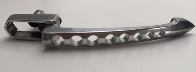
Paul’s next modification will be more obvious. Inspired by the Singer Porsches and 70’s racing bikes
he has taken “Drillium” (Google it) on board and has been busy machining a spare set of door handles.
You – Your Car
Thanks to all our contributors to this issue.
Contributions and feedback (positive or negative) are always welcome.
What’s happening in your garage?
Please make a few notes about your garage exploits and email them to me for the next issue.
Contributions are best managed by sending in plain text with attached photos or in Word format.
Mail your notes and pictures to: andrewawillmott@gmail.com
I am happy to hone rough notes (or even quite eloquent submissions) prior to publication.
Andrew W