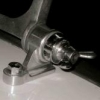
BlueTR3A-5EKT Posted February 19, 2022 Report Share Posted February 19, 2022 I have fitted hazard flashers to the car using a ‘kit’ with its own relay. The power supply is non ignition controlled and fused. The two wires from the hazard switch (left and right) connect to the bullets near the horn where the l & r control wires from the indicator switch connects to the main front loom. The system works as expected with the ignition off (or on). BUT If I have the indicator sw selected l or r & the ignition is off the rest of the ignition controlled system flashes in time notably the ignition warning light. I guess I need a diode I know the name of this one way device but have no idea of the size shape colour I should fit. Guidance please. Or one in the post for cash? Installation. I presume the diode should go on the circuit connection between the indicator switch and the standard flasher unit two pics of my wiring layout diagram mods. Thanks in advance. Quote Link to post Share on other sites
RobH Posted February 19, 2022 Report Share Posted February 19, 2022 Yes it's feeding back via the lead you have arrowed. PM me your address and I will put a couple in the post Peter - I've got loads of them and they are pennies so don't bother about it. Quote Link to post Share on other sites
Lebro Posted February 19, 2022 Report Share Posted February 19, 2022 I'm surprised you went to the trouble of fitting a dedicated hazard system Pete. If you have LED indicators (& I think you have?) you only need a three way changeover switch to do the job. Suitable switches on Ebay: https://www.ebay.co.uk/itm/264269001947?ssPageName=STRK%3AMEBIDX%3AIT&_trksid=p2060353.m1438.l2649 https://www.ebay.co.uk/itm/131898614717?ssPageName=STRK%3AMEBIDX%3AIT&_trksid=p2060353.m1438.l2649 Bob Quote Link to post Share on other sites
BlueTR3A-5EKT Posted February 19, 2022 Author Report Share Posted February 19, 2022 Thank you Rob for your kind offer of help. PM on its way. Bob, I had the period push pull self illuminating switch so built the ‘kit’ around that. It fills a hole in the dash quite neatly. Had I not already got the switch I would have followed your diagram and found the 3 way changeover switch. My only hesitation would be that under MOT test conditions I think a separate warning light is required for hazards. Hence the supply of ‘kits’ with built in warning lights for converting older cars. Thanks Peter W Quote Link to post Share on other sites
ianc Posted February 20, 2022 Report Share Posted February 20, 2022 Peter - if you had bought one of the Lucas (or look-alike) after-market Hazard Flasher kits, you could have followed the instructions given in my article in TR Action 132 (August 1996) or Section J9 of the Technicalities CD. As noted, the kits have the required flashing light inside the pull-push knob. Ian Cornish Quote Link to post Share on other sites
Ian Vincent Posted February 20, 2022 Report Share Posted February 20, 2022 My hazard lights use a similar circuit to Bob's and flash the regular indicator light. I've never had any problem with MOTs. Rgds Ian Quote Link to post Share on other sites
Lebro Posted February 20, 2022 Report Share Posted February 20, 2022 Mot man would never find my switch ! Quote Link to post Share on other sites
BlueTR3A-5EKT Posted February 22, 2022 Author Report Share Posted February 22, 2022 On 2/19/2022 at 7:52 PM, RobH said: Yes it's feeding back via the lead you have arrowed. PM me your address and I will put a couple in the post Peter - I've got loads of them and they are pennies so don't bother about it. Thank Rob the diodes arrived by post today Your included instructions on use are very helpful too. Thanks again. Peter W Quote Link to post Share on other sites
RobH Posted February 22, 2022 Report Share Posted February 22, 2022 The sketch shows the diode for positive earth Peter. I forgot to write that if you have negative earth, just turn it around. Quote Link to post Share on other sites
BlueTR3A-5EKT Posted February 22, 2022 Author Report Share Posted February 22, 2022 4 minutes ago, RobH said: The sketch shows the diode for positive earth Peter. I forgot to write that if you have negative earth, just turn it around. You quoted + ve earth in your instruction thank you. Now all I have to do is install the component neatly. Will heat shrink cause any issues to the component when ‘heated to shrink’ ? Cheers Peter W Quote Link to post Share on other sites
RobH Posted February 22, 2022 Report Share Posted February 22, 2022 See PM Peter. Heatshrink should be fine. Quote Link to post Share on other sites
BlueTR3A-5EKT Posted February 22, 2022 Author Report Share Posted February 22, 2022 Thank you for the guidance Rob. Quote Link to post Share on other sites
iain Posted August 21, 2022 Report Share Posted August 21, 2022 On 2/20/2022 at 9:42 AM, Ian Vincent said: My hazard lights use a similar circuit to Bob's and flash the regular indicator light. I've never had any problem with MOTs. Rgds Ian Hi Ian do you have a copy of the wiring diagram for your set up? Cheers Iain Quote Link to post Share on other sites
Ian Vincent Posted August 22, 2022 Report Share Posted August 22, 2022 12 hours ago, iain said: Hi Ian do you have a copy of the wiring diagram for your set up? Cheers Iain Hi Iain, My loom is a very non standard Advance Auto wire item from the US but as I said the hazard bit is similar to Bob’s. Unfortunately I don’t have a wiring circuit to hand as I’m away for a few days, I’ll try and sort one next weekend. Rgds Ian Quote Link to post Share on other sites
Lebro Posted August 22, 2022 Report Share Posted August 22, 2022 Quote Link to post Share on other sites
iain Posted August 22, 2022 Report Share Posted August 22, 2022 (edited) Hi Bob/Ian i was going to run with Bobs layout, however I think I’ve misinterpreted a comment above. Reading again I assume the indicator warning light does show the system working, it’s just the switch that is hidden from view? Iain Edited August 22, 2022 by iain Quote Link to post Share on other sites
Lebro Posted August 22, 2022 Report Share Posted August 22, 2022 Yes, the warning light is powered from the flasher unit directly, the flasher unit does not know whether you are flashing 2 lamps (indicating), or 4 lamps (hazards). So it will flash as normal when hazards are on. See posts above for details of where to get the parts required. Bob. Quote Link to post Share on other sites
iain Posted August 22, 2022 Report Share Posted August 22, 2022 Thanks Bob. I have the switch you recommended. Iain Quote Link to post Share on other sites
Drewmotty Posted August 22, 2022 Report Share Posted August 22, 2022 A few of us in the Devon Group are using this switch: https://www.ebay.co.uk/itm/323653487188?mkcid=16&mkevt=1&mkrid=711-127632-2357-0&ssspo=mLtSYuGbSIW&sssrc=2349624&ssuid=GeP3KodIRnW&var=&widget_ver=artemis&media=COPY It has an internal flashing indicator and is sort of Triumph related as it’s a Ferguson tractor part Quote Link to post Share on other sites
Lebro Posted August 22, 2022 Report Share Posted August 22, 2022 Would be interested to know the internal switching details, it's possible it could be used with my circuit. Quote Link to post Share on other sites
RobH Posted August 22, 2022 Report Share Posted August 22, 2022 16 minutes ago, Lebro said: Would be interested to know the internal switching details, it's possible it could be used with my circuit. Well the underside view shows the connections are DIN numbered, so should be like this (though that doesn't tell us what is going on inside): Quote Link to post Share on other sites
Lebro Posted August 22, 2022 Report Share Posted August 22, 2022 (edited) Need someone with an enquiring mind, a continuity tester, & a notepad ! Bob Edited August 22, 2022 by Lebro Quote Link to post Share on other sites
RobH Posted August 22, 2022 Report Share Posted August 22, 2022 (edited) This is how it is wired on the tractor (second page item F). I'm not sure that helps much either. I think the switch may have a flasher mechanism inside it. http://vintagetractorengineer.com/wp-content/uploads/2014/02/500-series-wiring.pdf (I obviously have too much time on my hands.....) Edited August 22, 2022 by RobH Quote Link to post Share on other sites
Drewmotty Posted August 22, 2022 Report Share Posted August 22, 2022 Extract from my wiring diagram. 30 Permanent live 15 Ignition switched live Quote Link to post Share on other sites
RobH Posted August 22, 2022 Report Share Posted August 22, 2022 Aah thanks Andrew. That is quite neat - does exactly the same as Bob's circuit but you get the illuminated switch with the right logo. Quote Link to post Share on other sites

Recommended Posts
Join the conversation
You can post now and register later. If you have an account, sign in now to post with your account.