qim Posted December 11, 2016 Report Share Posted December 11, 2016 (edited) I ordered uprated bushes from Revington http://www.revingtontr.com/product/rtr3492k/name/bush-kit-split-column-tr3-3b for my TR3A 1959 only to be told by my mechanic that they are for the TR4 and rereading the Revington page it appears that they are for the TR3B also, but not for the TR3A. However, the fitting instructions talk about TR2 to TR3A for the uprated Upper bush. Anyway, I am now trying to work out what parts I need for tightening the column. I remember that a few months ago the adapter coupling was tightened as it had play, but I cannot see anything in the catalogues other than the column itself and the adapter. Could someone throw some light on this, please? Thank you Camilo Edited December 11, 2016 by qim Quote Link to post Share on other sites
stuart Posted December 11, 2016 Report Share Posted December 11, 2016 I havent had a problem fitting them and FWIW The column on a 3B is the same as a 3A one. Stuart. Quote Link to post Share on other sites
qim Posted December 12, 2016 Author Report Share Posted December 12, 2016 And what are the standard parts that go in the middle of the split column? There is the adapter, and what else? Do the bushes go here? Quote Link to post Share on other sites
foster461 Posted December 12, 2016 Report Share Posted December 12, 2016 And what are the standard parts that go in the middle of the split column? There is the adapter, and what else? Do the bushes go here? In the split column steering as on the TR3A there are two rubber/metal/delrin bushes (the TR4/TR6 style with the rubber ears that lock into the outer tubes). There is one of these in the bottom of the upper tube and another at the top of the lower tube, the one attached to the steering box. At the top of the upper tube, the end nearest the steering wheel there is a felt bush that needs to be soaked in oil before installing. Connecting the upper and lower inner columns is the splined connector with the two locking bolts. There is a rubber plug in the lower outer tube just south of the connector for adding the correct steering box lube. As far as I know that is all there is and it sounds like you need to get a proper workshop manual. Stan Quote Link to post Share on other sites
qim Posted December 12, 2016 Author Report Share Posted December 12, 2016 Connecting the upper and lower inner columns is the splined connector with the two locking bolts. Stan This is what I was after. So, if there is play that you can't get rid of in the splined connector, the chances are that either connector or the top or bottom columns need replacing. Is that it? Is it likely? Thanks Camilo PS - I do have a workshop manual but thought that these bushes went where the splined connector is. From what you wrote that is not the case. Quote Link to post Share on other sites
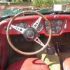
foster461 Posted December 12, 2016 Report Share Posted December 12, 2016 Here's a picture from a google search You can see the "ears" of the rubber/steel bushes poking through the upper and lower outer column. If you are observing movement at that splined connector (ie the upper is rotating but the lower is not) then that would be unusual and I would investigate. If the splines are not worn out make sure the clamp bolts are tight. There are flats on both inner columns so it is hard to assemble that coupling incorrectly. Stan Quote Link to post Share on other sites
qim Posted December 13, 2016 Author Report Share Posted December 13, 2016 Hi Stan Sorry for being so dumb... I cannot see what you refer to as "ears" Looking at your pic and a few of the books that I have (that hardly show the split column) I cannot see where the bushes mentioned in my OP go. I guess one goes on top and the other two "either side of centre coupling" according to an old Moss catalogue. From this, I take it that in your pic those two are inside the Outer Tube, but your reference to "ears" gets me confused. Thanks Camilo Quote Link to post Share on other sites
stuart Posted December 13, 2016 Report Share Posted December 13, 2016 Hi Stan Sorry for being so dumb... I cannot see what you refer to as "ears" Looking at your pic and a few of the books that I have (that hardly show the split column) I cannot see where the bushes mentioned in my OP go. I guess one goes on top and the other two "either side of centre coupling" according to an old Moss catalogue. From this, I take it that in your pic those two are inside the Outer Tube, but your reference to "ears" gets me confused. Thanks Camilo The "Ears" Stan is referring to are the small rubber buttons you can see sticking out of the main tube sections either side of the joint.That is the location of the bushes. If you have a bush in your hand you will see them. Stuart. Quote Link to post Share on other sites
Motorsport Mickey Posted December 13, 2016 Report Share Posted December 13, 2016 (edited) Hi Camilo, Stan reference to ears I think refers to the rubber locating lugs which are on the outside of the bushes (the bushes have one either side from memory like errr...ears !). If you inspect the picture you can see about 15mm INBOARD from the split in the top and bottom tube there is a black disc, the one in the right hand side tube is viewed from about 90 deg and is positioned at the bottom of the tube edge wise on, only visible as a line almost with only a small amount of quadrent visible. The one on the left is likewise about 15mm inboard just above the frayed area of the hose and more visible as a disc or round defined shape. Mick Richards Edit: Sorry, wifely mutterings made me adjourn before posting and Stuarts beaten me to it. Edited December 13, 2016 by Motorsport Mickey Quote Link to post Share on other sites
foster461 Posted December 13, 2016 Report Share Posted December 13, 2016 Sorry Camilo, hopefully the clarifications above will have answered your question but if there is still doubt the rubber protrusions in this picture (I have marked one with a red arrow) are what I was calling "ears". They lock the bush into the ends of the upper and lower outer tubes by popping out through the corresponding holes in the tubes as you can see in the earlier picture of the column and connector. Quote Link to post Share on other sites

Recommended Posts
Join the conversation
You can post now and register later. If you have an account, sign in now to post with your account.