


angelfj
-
Content Count
1,500 -
Joined
-
Last visited
Content Type
Profiles
Forums
Calendar
Posts posted by angelfj
-
-
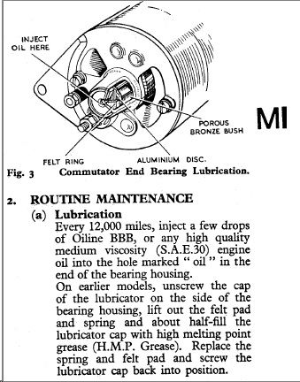
But when would the need for oiling arise after a rebuild?
If the rebuild included a new bronze bushing let's hope the shop knew how to prepare it. Over here we call this type of bushing oilite, a trade name for a porous bronze material developed by Chrysler Motors in the 1930's. We usually soak them in hot oil for an hour before pressing into place.
-
Can someone educate me on the proper oiling of the generator? I am using the original generator and control box (rebuilt at the same time by Cox) and it has worked fine ever since the rebuild. I have no ancillaries other than standard ones, and no heater. But when would the need for oiling arise after a rebuild?
Cheers
Dan
-
Making progress. Re-wired the regulator per the wiring diagram. Now, it tops at just under 20amps. But still rises quite a bit on revs. That being said, the battery was only 12.4v at rest, so I am charging it once again.
This is good news and indicates that the regulator is limiting charging current to approximately 20 amps. Your making progress.
-
Regulator was through a guy here in the states that is well known for building the boards for converting the coil set up.
He inquired as what "dynamo" I had and to be honest, there was not a single case stamping I could find on it for him. We anticipated it was a replacement type with this figures:
The original Lucas dynamo fitted was model C40-1, part number 22700.Details from the Workshop Manual are as follows :Model : C40 - 1Type : Two brush, two pole, compensated voltage controlRotation : ClockwiseField resistance : 6 ohms approximatelyMaximum output at 13.5 volts : 22 amperes at 2050 - 2250 r.p.m. (connected to a load of 0.61 ohms).Brush tension : 22 - 25 ozs. (0.62 - 0.71 Kgs).Minimum brush length : 11/32" (9mm)Did you have similar problems not knowing your dynamo wasn't the Lucas specs? I just tried to take a reading at the regulator from the brown/yellow and brown/blue coming off the dynamo and was getting MV readings, not even a V? But when I rev'd it, the battery readings would go from 12.7 to 14.2?
F1loco, I'd love to be able to assist you, but not sure that car you have. Your icon is a TR4 or 4A, I think. The TR4 utilized a C40, with maximum rating of 22 amps. So, the current limit should not be set above 22 amps.
Still not sure who supplied your regulator. Mine came from Bob Jeffers of Wilton Auto Electric, Wilton, New Hampshire.
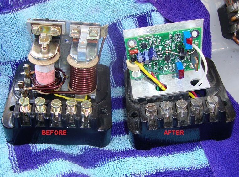
Does your solid state regulator look like this (the unit on the right)? http://i135.photobucket.com/albums/q159/angelfj/My_installation_1_DSC07015.jpg
What do you mean by, " boards for converting the coil set up" Do you mean ignition coils? I don't believe Wilton do anything with ignitions.
I have/had an original LUCAS C39PV2, with large letters stamped on the case, fairly easy to read. The aftermarket LUCAS-type units have no markings on the case.
Another very important question, which LUCAS control box did the solid state regulator replace? The TR4 would have had the LUCAS RB106-2 fitted. Is this what you had?
There are two terminals on your dynamo. The larger terminal is the armature circuit and is connected by a Yellow/Green wire to terminal 'D' on the regulator. The smaller dynamo terminal is the field, connected by a Yellow wire to terminal 'F' on the control box. There should be NO appreciable voltage between these two terminals.
-
Frank, your bearing failure could be from an over tight belt, woulden't be the first time?
Graham
Graham: Your correct for sure and that was the first thing we checked. Our belt was in proper form.
Cheers
-
Then, can you elaborate on how the 16% variation in output can be detrimental? This is interesting and as I said, either I know or not and when I don't know, I ask.
Badfrog
Sure! In this particular case a few assumptions are necessary. From the perspective of the battery, if the battery is already compromised such as in the case of a bad cell, further forcing a high charge current could buckle the plates, over-heat the electrolyte and possibly cause an explosion. Not good at all. From the perspective of the dynamo, if the current limit is set too high, the dynamo would try to supply current beyond its design limit. For example, according to LUCAS literature , Triumph selected the C39 design based on an average demand not exceeding 16 amps. This dynamo has a maximum output of 19 amps. Back in the days when our cars were produced, this dynamo was adequate. Things are different now and with modern enhancements its easy to exceed 19 amps. However during my recent trip to North Carolina, I figure I was running somewhere near 20 amps continuous, due to the use of main beams, heater/fan, windscreen wiper, etc. The current limit had been incorrectly set (my error) at 22 amps. This allowed my dynamo to run in overload most of the time. The current limit setting should have been 19 amps. If electrical loads required more than 19 amps, the battery would eventually run down to a point requiring an external charge.
-
I usually only talk about what I know. Please remember this.
It was your generalization that attracted my attention. Regardless of what you have experienced, many Chinese built devices are completely tested during production. Having prepared production testing specifications and quality control procedures as well as automated production line testing, I can assure you that your generalizations are not appropriate.
-
Ok so my ammeter was "bit bouncy" and figured it couldn't hurt to do the solid state switch. So I got back and installed today. At idle, it just +1-5, and as soon as put the lights one, it goes (-) - so I figure great. Problem is if I even feather the gas, it pegs on the meter at +30??? IS this an issue I need to be concerned about? I switched the car off for fear of frying my system?? Suggestions of attack?
Where did you buy your regulator? Read my reply to badfrog. its important to have the current limit set properly or you will destroy your dynamo. As others have stated, the charge rate you describe indicates a battery that is discharged. One thing you can try is to have the battery checked and if necessary charged and reinstall. If that doesn't work, then I suspect the regulator needs to be adjusted or replaced.
-
Too low. Should be 14.8V. So the charging system is working full blast to compensate. Once the battery is charged, it should go back to a slightly positive current.
Badfrog
No, that's not correct. All modern 12 volt batteries, regardless of design, have a cell voltage of just over 2 volts. To be more precise:
- Open-circuit (quiescent) at full charge: 2.1V 6 x 2.1 = 12.6 volts
- Open-circuit at full discharge: 1.95V 6 x 1.95 = 11.7 volts
- Loaded at full discharge: 1.75V 6 x 1.75 = 10.5 volts
You may be thinking of the typical alternator output when charging a discharged battery.
For example:
- Typical (daily) charging: 2.37V to 2.4V which gives you 6 x 2,4 = 14.4 volts
-
China-built electronic devices are not checked at the end of the production line. It is the buyer that does the checking.
Your generalized statement is absurd! That said we don't even know where he bought this SS regulator. If it is the Bob Jeffers design you can be sure it was assembled and tested in New Hampshire, USA. If you read my recent posts regarding a dynamo failure, you will note that I was too quick to point a finger at the regulator as the source of trouble. In fact it was a bad dynamo all along. Getting back to the regulator, it is important to identify the dynamo and its maximum current rating. I made a mistake and had identified mine as a LUCAS C40 when in fact its a C39PV2. This resulted in a current limit setting (made at the factory) approx. 16 percent too high. Depending on one's driving habits and use of electricals, etc, this can kill a dynamo very quickly. Bob Jeffers was quick to point this out and we got the setting sorted.
-
Tom: Sorry for your experience, but glad that this didn't cause a serious road accident. It is true that what you experienced is not common, but statistically somebody gets hit. Do you have an idea of how many total miles are on this engine? Were there any major bottom end repairs?
A friend of mine at college drove a mint condition TR4. This car enjoyed a better life than he did, and he was meticulous about maintenance. At approximately 100K miles, the crank broke cleanly at a point between the 2nd and third cylinders at the bearing journal. Unbelievable, that the engine continued running, but of course, no power at the flywheel. He was ab;e to save the engine, rebuilt it and he was back on the road by the end of the term!
Yes, tough little engines.
-
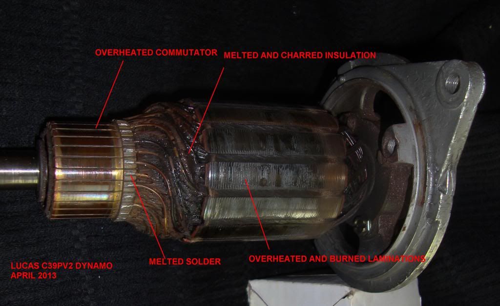
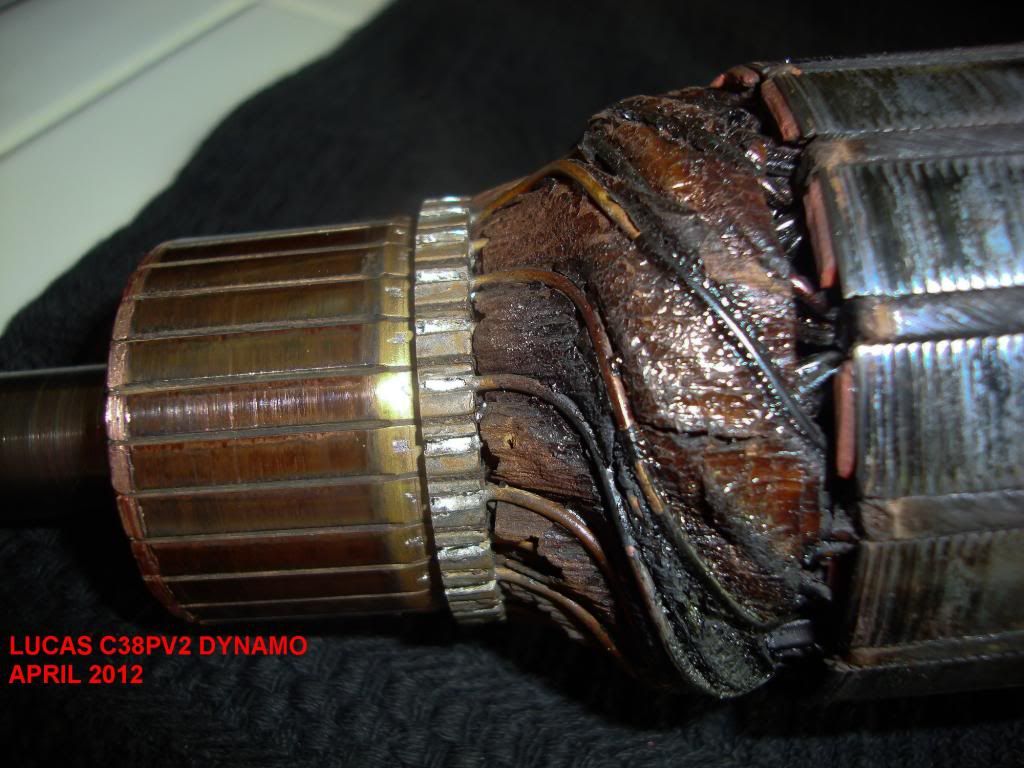
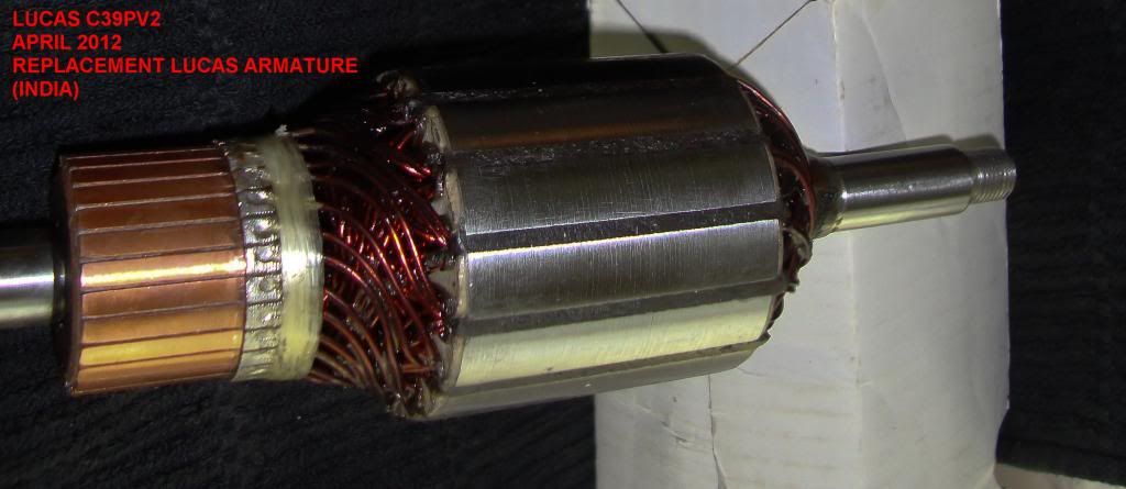
Well we spent a couple of hours Thursday evening removing the failed generator and installing the backup. The backup runs great.
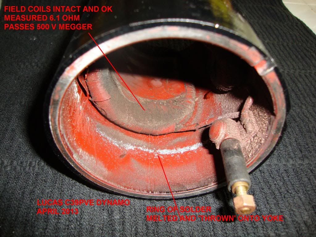
As far as the bad one goes, the armature got completely toasted and roasted. The copper winding got so hot that the insulation is burned black! The silver solder which connect the windings to the commutator got so hot that they melted producing a solder ring around the inside of the yoke.
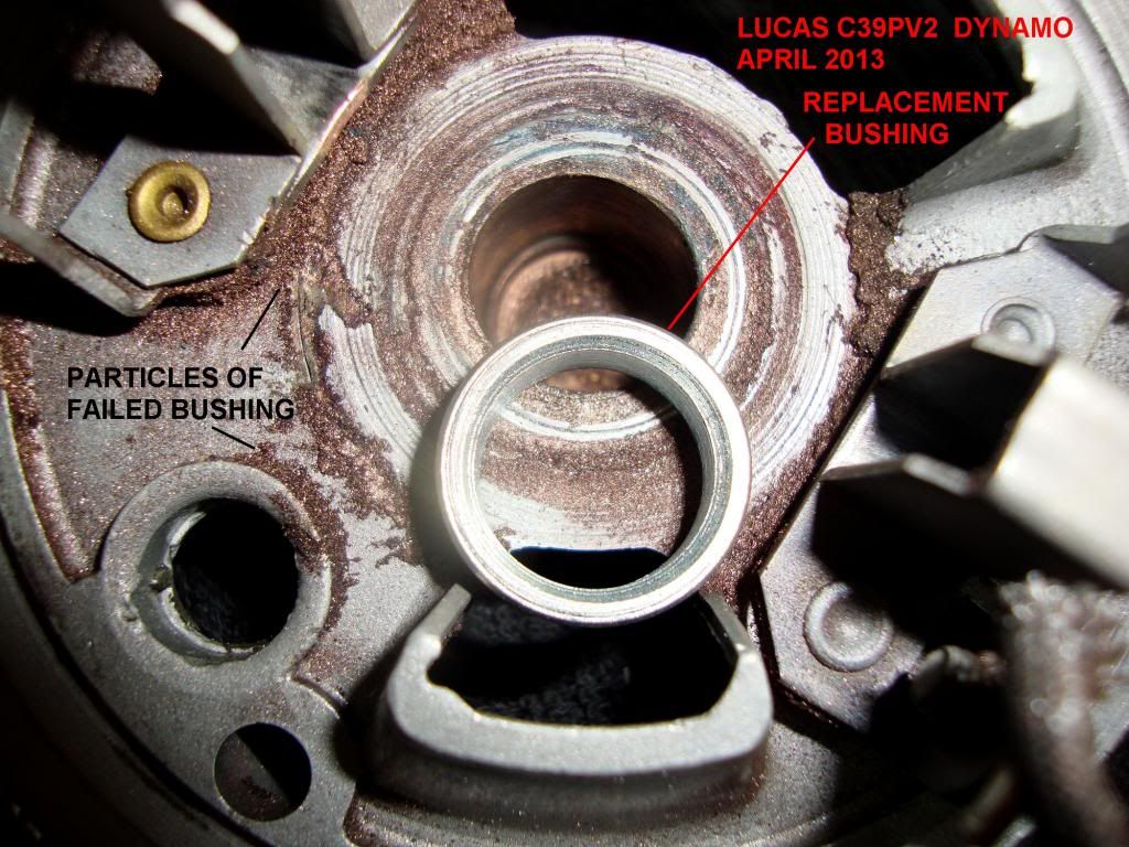
The shaft has a distinct wobble and I believe the rear bushing failed because it was not properly oiled. The hole in the bushing is now egg shaped and that end of the shaft is not round anymore!
The unit was serviced by an auto electric shop a few years ago and put in storage until we needed it. Our theory is that they forgot to soak the 'oilite' bronze bushing in oil prior to installing it. This caused premature bushing failure and subsequent failure of the commutator, arcing, high temp, ect, etc. Too bad because this particular shop had done several dynamos and starters with excellent results. Note: The replacement armature came with a steel replacement bushing. We do not intend to use this and will fit a proper 'oilite' bronze type.
This failure spared the field coils which measure in spec at 6.1 ohms. I meggered (500 volt) the windings to earth and they pass.
Obtained a new armature (Lucas India) plus bushing and brushes from Moss USA to put in this unit and use for a spare.
Additional thoughts: The suspect solid state regulator was a red herring. There was never anything wrong with it. It was returned to Wilton who tested it and verified it and OK. A clarification is in order. When I first ordered the unit I made an error in describing my dynamo as a C40. This resulted in a current limit setting of 22 amps. The C39 has a maximum capacity of 19 amps. Thus the regulator allowed a 16 percent overload which probably helped to cook the unit
Here are some photos.
-
New Development! I returned my Wilton Auto Electric control box late last week. Got an email from Bob Jeffers yesterday stating that he has tested the solid state regulator unit and it is working perfectly! Bob suggests that it was the dynamo all along.
We found a spare C39PV2 dynamo.
Using jumper leads, we connected this to the car as a substitute to the in situ one.
Flashed the field.
With everything connected and ready, switched on the IGN.
Red light came on which is correct.
Using a heavy duty electric drill, we spun up the spare dynamo and the red light went out.
This indicates that the spare dynamo is OK and the spare original style control box is OK.
So friends, I was fooled into believing that the solid state control box caused the charging system to fail.
Hat's off to Bob Jeffers for his advice and solid product.
Tonight we replace the bad dynamo.In a few days I hope to report on the autopsy of the failed unit. The field coils tested OK so I suspect a bad armature.
Stay tuned.
Frank -
Hi Frank & All others,
My petrol winter storage method is just based on pure experience with petrol of now addays. My 3A will NOT start with "wintered" petrol. Perhaps our mutual petrols are differently composed ...? (These problems did not occur before modern petrol was introduced).
Despite each and every ones good and well respected advice: new petrol asks for new insights...
But nevertheless, we must continue such interesting discussions!
Regards - Raymond
Raymond - always the diplomat/gentleman. Thanks
No doubt though that fuel formulations over here are quite different - even from state to state!
Cheers, Frank
-
Measurements taken recently, with the proper Mk8 Avo meter shown in the WSM.
Actually on a 4A. Dont think a sidescreen will be much different.
Main Beam 10 surge 30A?
Dip Head 8 ditto
Side lights 1.5
Stop lights 3
Flashers 1.8
Horn 8.5
Start solenoid 4.5
Wiper 3 slow-speed
Back in the 60's most UK cars had these dynamos we all knew that lights, heater fan, wipers would most likely take you into a battery discharge condition.
This is in fact why the cars were fitted with ammeters. You were meant to trim the load to keep the battery charging.
We also knew that the charging regulation would allow the battery to be damaged if it was flat. So if you took a jump start to get going you would put the headlights on to get the current down. I still do this actually because my modern car does not display current of course.
I have a dim memory that typical rally cars were fitted with two dynamos.
Many thanks Alan. Gee, they must have needed a shoe horn to get the second dynamo in!
-
- Has anyone added up or better yet measured the total connected electrical load for a typical sidescreen TR ? Actually I was curious how Triumph decided which Lucas dynamo to fit to these cars. I discovered recently that the C39 dynamo (18 amps?) may not survive very long with sustained use of heater, wipers, main beams, and certain safety enhancements.
- Considering the modest capacity of these dynamos does anyone know if a heavy duty dynamo was offered. I find it hard to believe that the works cars, in particular the rally cars could ever function with the limited capacity of a C39 or C40.
Cheer,s
Frank
-
Don, Raymond, Viv, et al: I truly respect your collective advice/recommendations, BUT putting a car up for the winter with and empty fuel tank seems to be contrary to just about every enthusiast website/magazine, e.g. Car & Driver, Road & Track, Hot Rod, etc.
Why do you suppose this is so?
-
Finally, finally! Sun and high temps at last! Sure, last weekend was great, but I had to store my car elswhere over the weekend because my driveway had to be repaved. That job's done and now it was time to get the TR out of the barn.
Not without a few glitches! First, after checking all vitals, I took the car down the road for a fresh MoT. No problem off course. When I returned from my 3 mile trip, I noticed that bowl of the front carb leaked. The large nut under the carb had loosened itself and petrol was seeping out. I retightened the nut, but I'm a little worried about the fact that I had never noticed it before and I'm puzzled how I can prevent it again.
Second problem: In October, I stored my car with a nearly empty fuel tank (alloy tank, no worries about rust etc), so my first trip with the fresh MoT and the retightened nut, was to the fuel station for a fresh dose of Shell V-power. The car runs great with the fresh fuel. But it often sounds 'lumpy' at tickover (900 rpm), despite a 123ignition - in fact, 123 didn't improve it. I replaced the spark plugs, checked all high and low tension wiring and finally looked at the ignition (static timing) I've advanced it a little. Things look to be better, but I'm not convinced when I hear the car next to another TR. A new coil perhaps?
Finally: as said I layed the car up for the winter with a nearly empty tank. I'm sure that the dial on the dash was correct when I parked the car. Today, the needle told me(...) that the tank was completely filled - even with only 3 ltrs in the tank. Not good.
Now, three giltches. I'm always interested to read your answers / ideas. If you happen to have one, please share it with me (and others off course).
Oh and did I tell you that I enjoyed every minute behind the wheel of the TR?
Menno
Menno, This is my opinion but not to say that there might be other issues to sort. Let's focus on the third paragraph which describes how your car was stored with an almost empty tank. Storing a car with empty fuel tank in never a good idea. Unless you replace the air in the tank, above the fuel with dry nitrogen that is! The moisture in the air will condense on the walls of the tank once the temp gets below the dew point. Of course the more empty the tank, the more water can condense. Trying to run fuel with water mixed can provide a false indication of ignition and/or carb trouble. So, next "end of season", fill up the tank at your favorite station and add a little fuel stabilizer and marvelous mystery oil and dream of spring.
p.s. Take a look at the clear glass sediment bowl, integral with the mechanical fuel pump. Quite often you can see a layer of water at the bottom of this bowl. Just loosen the nut and dispose of the fuel/water.
-
Hi Frank,
Company Is London and Essex Auto Electricas Ltd.
ebay item 281092522551
Only difference is the post that exits from the body rather than the end its further away from the exhaust.
Typically used on Ice cream Vans for the fridges and PA system.
Works for me with original Lucas regulator but not for the dedicated Concours enthuisiast maybe?
rgds
Rod
Many thanks! I will definitely check this out!
-
Hi Frank,
I am with Ash on this one. What was your reason for going to solid state and particularly on a sidescreen where the scuttle shake is commonly known? I am really interested in the answer.
What you have is a thinly disguised fake or ersatz unit which possibly has vibration issues centred around the constant for 1000's of miles.
When restoring a TR with Lucas electrics you must ensure that you fill the Lucas black smoke box that is characteristicfor the period.
Personally I would go back to a rebuilt Lucas regulator and an uprated Dynamo for originality and wait till the unit is proved to be reliable. I have an original regulator and a 35amp dynamo which seems to be more than adequate for all my needs.
If you want or need a lucas smoke box let me know as I have two or three spares. The best information is that the rebuilt original is the best way as repro ones are not built with the quality of the "old" material.
Cox automotive are consideredto be "old school" and rebuild this stuff routinely.
http://www.coxautomotive.co.uk/supports.html
Rgds
Rod
Tell me Rod, as I am not aware of a 35 amp Lucas generator that would fit a 1959 TR3A. The standard unit produces maybe 18 amps!
-
I appreciate the discussion and I would be a hypocrite if I suggested that I had no concern for originality, which was as most of you that have followed my trials and tribulations, the main theme of my restoration project
I was attracted by the Bob Jeffers, Wilton Auto Electric design because it was a do once and forget improvement. It has the added benefit of stealth and can not be discovered by concours judges. Conversely, I was frustrated by the difficulty in keeping the original Lucas box in proper adjustment. Anyone who has followed the Lucas documentation can appreciate what I am stating.
To be fair to any regulating system either solid state or electromechanical, my Lucas generator was subjected to almost constant overload during this recent trip. Even a wide-open regulator can not compensate for an inadequate electrical source. With, heater fan, headlights and windscreen wipers running simultaneously, now add the enhancements I made for safety. I have added an extra brake light (incandescent) which attaches by magnets to the surface of the boot lid, just below the fuel filler. We also changed the wiring so that when you step on the brake, five rear lamps lite, that is, tail lamps x 2 + indicators x 2 + new extra brake light. These lights are all incandescent. Another change has both the tail lights and indicators flashing when making turns. We also now have true 4-way emergency flashers. In an emergency, I can flip a small toggle switch to activate the flashers. Then everything flashes, front and rear indicators and brake lights. Except for the emergency flashers which I only used once for about 10 minutes, I was constantly using other new features thus taxing the regulator , generator and battery.
To be fair to Bob Jeffers, he only recently became aware of the resistor problem in his solid state design. I suppose that most drivers using his system don't drive over 3 - 4 hours at a time but rather take their cars out for an afternoon of spirited motoring down the highway. I am anxious to get my solid state unit back from Bob. When I do, I'll provide a follow-up to this post.
Cheers, Frank
.
-
The Grey Lady and I just returned from "The Gathering", an annual event set in the rolling hills of northern NC. This was the Lady's first long distance trip at something less than 1500 miles round trip. See posting in Main Forum with link to photos.
During the second day the IGN light suddenly lit. It was not a flicker. It was easily noticeable in full daylight. I should explain that due to intermittent heavy showers and cool temperatures, I was running with full head lamps, heater/fan and GPS/cell phone charger. Needless to say my little Lucas generator was hard pressed anyway. I managed through the weekend by charging the battery each night. A full charge and judicious use of lights, heater, etc. got me through the day. I left for home early Sunday morning with a full charge and brilliant sunlight so headlamps were not required. However, I was somewhat anxious of the 600 mile trip before me. I realized that the ignition system did have a minimum voltage cutoff. Was it possible to male it home before the sparks stopped jumping across my vintage Lodge plugs?
Two more stops - one for fuel - and a second for biological needs (I'm now 65 years old). During the second stop, I had to turn off the engine due to security. When I attempted to re-start the engine the battery was so low it could not turn the starter. Fortunately some local chaps gave me a push and I got started.
Fast Forward - I finally arrived home at 5pm. I was dam curious! So I got the digital voltmeter and measured the battery voltage . . . . . . . . 5.86 volts - AND during the final 20 miles there was a distinct loss in power, no doubt, due to reduced spark voltage. So, there it is, empirically established that the minimum ignition voltage is something perhaps in the range of 5 - 5.5 volts, depending on many factors like temp, compression ratio, etc.
Epilogue: The failure was due to a bad resistor on the printed circuit board in the solid state voltage regulator.
http://i135.photobucket.com/albums/q159/angelfj/My_installation_1_DSC07015.jpg
I spoke to Bob at Wilton Auto Electric this morning. He said that he has determined that the resistor in question only overheats on long trips, more than 3 hours or so. He was happy to offer a quick turn-around on an upgrade. Until the unit is returned I will use my old Lucas unit. Isn't that ironic!!!
-
not sure how the older AC diaphragm will hold up with the local E10 fuel. I imagine the Powertune kit sold here is designed for it. The diaphragms that I took out were original AC and they were pretty rigid.
The fuel pump in Grey Lady is a NOS AC pump that we rebuilt. However, we did not use the RED diaphragm included in the rebuild kit. First of all the original diaphragm looked OK and the color of the new one wasn't correct. Our assumption turned out to be WRONG. Either the original BLACK diaphragms are incompatible with modern fuels or they just plain fall apart due to age. Ever since last June, when the restoration was finished, I have been plagued with bits of old diaphragm getting under the jet/seat of the float bowl. This results in a very serious and sudden loss of power either by fuel starvation if the jet gets stuck closed or flooding if the jet sticks open,. It's amazing how much **** of significant size ends up in the bottom of the float bowl. Grey Lady is at Brian's shop this week to have a new BLACK diaphragm installed + other minor maintenance issues corrected.
Moral of the story: do not install aged fuel pump diaphragm. John S at TRF has rebuild kits with new BLACK diaphragms in stock.
Cheers,
Frank
-
One word - HIDEOUS!
speedometer issues
in TR4/4A Forum
Posted
No, not necessarily. Sometimes the inner driven cable backs away from the engagement point in the speedo. Check that end of the cable again. There should be a metal or plastic retainer which is intended to locate the cable. Too far forward and you damage the speedo, too far back and the cable disengages. Check to see of the retainer is there and/or if it has moved.