

Tr4aJim
-
Content Count
515 -
Joined
-
Last visited
Content Type
Profiles
Forums
Calendar
Posts posted by Tr4aJim
-
-
I mounted a “cigar lighter” type socket inside the glovebox. It has its own inline fuse. I then put a dual USB adapter in the socket as that is my most common use, however I can still use any other similar accessory as needed. The reason I mounted it in the glovebox is I use the open glovebox door as a shelf to hold my phone (I have a suction cup style holder the sticks very well to the inside of the lacquered door). With the glovebox closed, everything is neatly tucked away.
But on to the more important question………the speed limit in Wales is 20 mph?!?!
 Hell, here in New Jersey you’d get arrested as a road obstruction doing 20! Although I must admit drivers in NJ are considered to be, shall we say, “aggressive” drivers.

Jim
-
Ian, could it be the difference in the clutch bearing used between the 4 and the 4A? For example the 4A doesn’t use a clutch lever return spring, and the 4 does.
BTW - the Moss US web site lists a clutch lever return spring for the 4 and the 4A. However the Moss UK site only lists the spring for the 4 (correctly so per the 4A Stanpart catalog).Jim
-
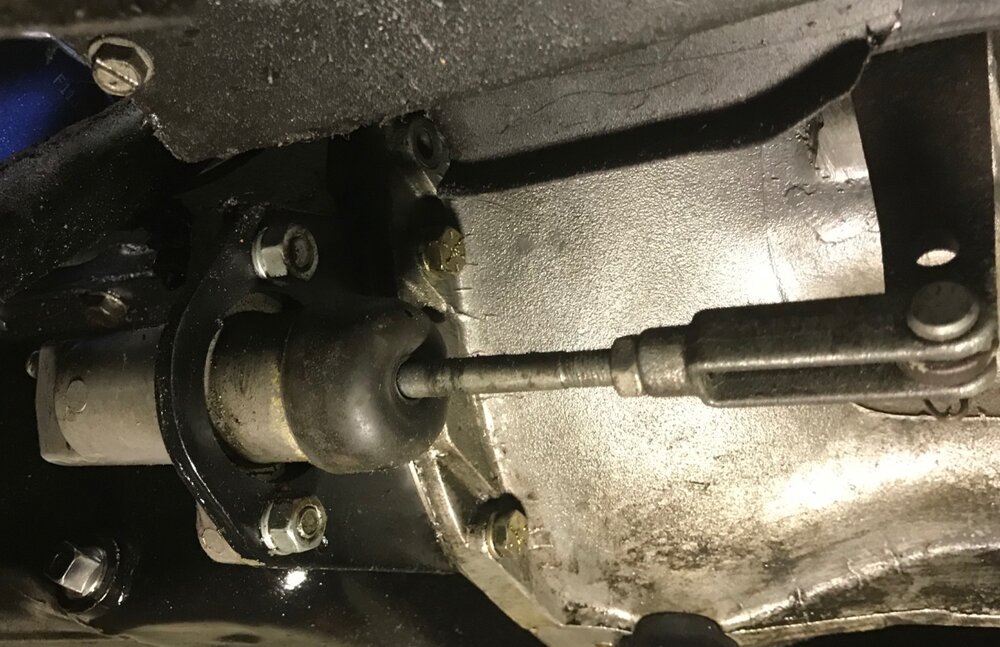
Just as Marco says: on my 4A I have the push rod on the lowest hole, as that lines up with the bore of the slave cylinder.
Jim
-
Something else to try is “Magic Eraser”. A friend uses it on the vinyl seats of his boat to good effect. As always, try it on a small/less visible spot first.
Jim
-
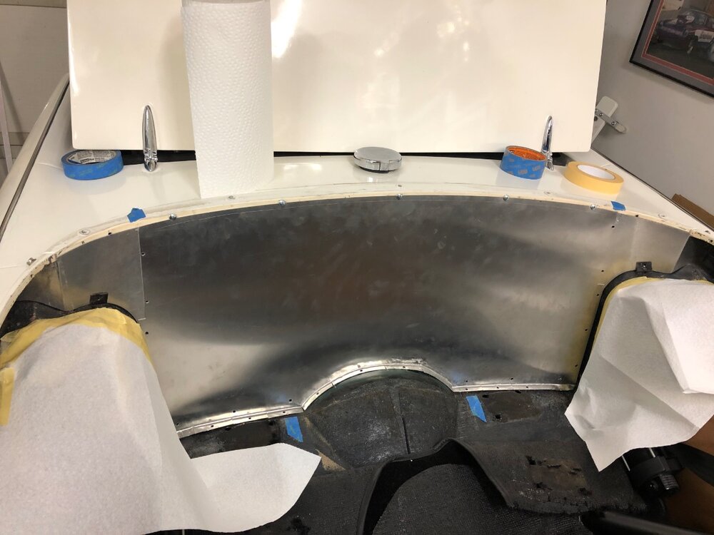
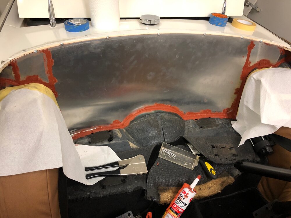
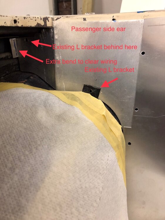
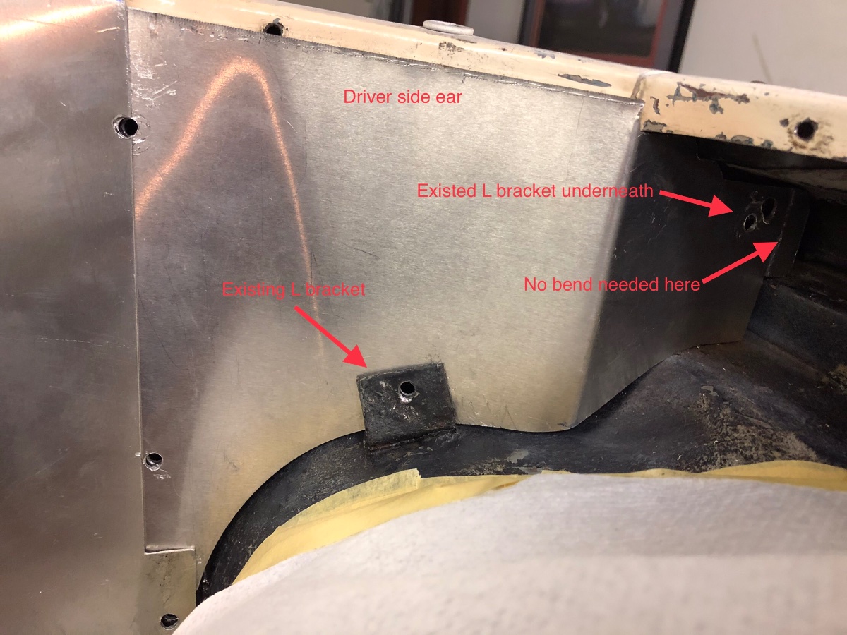
I put the Revington kit in my 4A. I sealed all the joints with 3M “fire-barrier”. The hardest part was getting a good fit in the upper corner “ears”. I added pictures with details of these pieces. Also I did this with the interior already in place, so that added to the complexity. I had to peal back the wheel arch covers a bit. I am no metal worker, so if I can get this to work, anyone can.
Jim

-
Alf, here ya go-
If you don’t need 25 feet, contact the seller and ask for what you do need.
Jim
-
Alf, this is the eBay (US) shop where I purchased my wire. They have a wide range of colors/stripes. Though a lot of their listings say 25 feet or more, I messaged them, and asked for 5 feet for some of the runs. They said sure and adjusted the prices accordingly.
https://www.ebay.com/str/4rcustomsJim
-
Alf, I did not install a separate fuse for the wiper motor as I saw that the TR6 did not use one for that motor. However, when I added a “cigarette lighter” socket to the inside of the glovebox (primarily to plug in a USB adapter), I ran a separately fused white wire off the fuse box for it (I did the same for the electric fuel pump in my car). I don’t have a radio in my car, as I use my phone and a Bluetooth speaker.
+1 Bob, I also sourced my striped wires from eBay (US). I contacted one of the suppliers, and even though they were advertising only 15 foot lengths, they said they could supply any length I needed.
Jim
-
Alf, on my LHD 4A, picked up the switched power (green wire) under the dash in the right side footwell. Near the top of the heater box I found three green wires “spliced” together by one of those 4-way connectors. I ran a new green wire from the the 4th position in that connector, down to pin 4 on the modified wiper switch.
Jim
-
Don’t feel bad Phil- when attempting to modify my switch, and had separated the two halves, I proceeded to immediately drop it on a concrete floor (scattering bits everywhere)!


Jim
-
Sorry, I don’t recall the position on mine either. However when I ordered it from SVC, I had to specify RHD or LHD. If you had to do the same when you purchased yours, it should be good to go.
Jim
-
FYI - Not sure if this applies to RHD cars, but several years ago we had a discussion on the US TR forum about choke cable routing n the 4A. Apparently folks who had 4As with stock HS6 SUs, had an additional hole in the upper bulkhead, up near the bonnet latch. We surmised that this was due to how the HS6 choke cable routes/attaches to the top of the carb, while on previous carbs, the choke cable routed/attached from underneath. My 4A doesn’t have the additional hole as it didn’t come with HS6s originally.
Jim
-
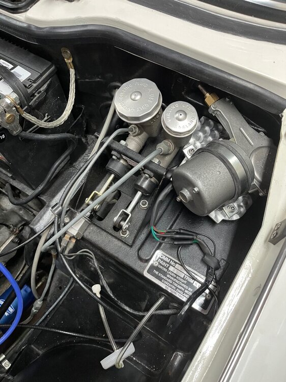
Phil, your plate/install looks great! Man, I wish I had that much space around my motor! Sorry, can’t help you with the VS.
Jim
-
IT WORKS!!!!!!!
As usual, the problem……was mine. I always take the battery out of my car over the winter, on a shelf with a trickle charger. So for tinkering, I use a 12 volt power source that I’ve had for years. I used it for this. To try and isolate the problem, I put the motor on the bench, and with no switch, connected the motors green and green/red wires together. I added the 12 volt supply, and got slow speed. I then connected the motors green and blue/green wires together and still got slow speed!
After cursing the names of several old deities, I decided to pull the car battery off the shelf and try that test again.
VOILA - TWO SPEEDS!Apparently that old 12 volt supply isn’t, or it’s not pushing enough amps, or whatever - anyway it’s in the bin!!
I installed the motor back in the car, hooked the motor wires up to the cars wiring, and Rogers switch, and it all works like a dream!
Thank you all for the gracious help and most of all - patience!
Jim
PS - RobH - on the motor I have, those yellow, red, and blue wires are set right into that plastic piece. No connectors as in your picture.
-
RobH, you were right!! I used a continuity tester on the motor contacts, and found the following contacts were connected inside the motor:
1&2
1&4
2&4
3&5
So the blue/green wire is somehow connecting to the red/green wire inside the motor. I’ll let the motor rebuilder know. Thanks!
Jim
-
Roger, no, the motor came with the connector/wires: black, green/white, brown/green, red/green, and blue/green, which I imagine is just like the Moss loom.
Using the Moss switch wiring chart that RobH provided earlier as a reference,
(https://www.moss-europe.co.uk/media/pdf/155496_instructions.pdf)
I ran two tests bypassing the switch and wired the motor directly:
- I only connected the motors green/white wire to its red/green wire (simulating switch connector 4&6) , and added 12 volts to that connection. The motor ran at slow speed.
- I then only connected the motors blue/green wire to its green/white wire (simulating switch connections 4&8), and added 12 volts to that. The motor ran at slow speed.
I bought the motor from an eBay wiper motor rebuilder who specializes in British cars, and came with good references. So I notified him of the issue, and waiting to hear back.
Jim
-
Roger, the switch feels fine with obvious detents, and as I mentioned in a previous post, the connections between terminals is as follows:
switch all the way in - pins 2&6 connected (brown/green to red/green)
switch pulled out to first position- pins 4&6 connected (green to red/green)
switch pulled out to second position- pins 4&8 connected (green to blue/green)
With the exception of the new blue/green wire I ran, all other wires are from the stock 4A loom (I tapped power off the green wire going to the heater fan).
Im going to try and connect the switch directly to the motor’s wires, to verify no issues in the 4A loom.
Jim
-
In the immortal words of Dr Frankenstein (and Gene Wilder) - IT’S ALIVE!!!
The TR6 motor, with Roger’s modified switch, works! This is with the stock 4A wheel boxes and a 90 degree gear in the motor. Now I just have to tidy up the wires.
However……….
I don’t notice any real difference between the two speed positions. Is that just the way they were, or could I have something wired incorrectly?
Jim
-
Phil I’m right behind you! I plan to finish my install this weekend as the temperatures will finally be above freezing!
Jim
-
Phil I’m using a 16 gauge wire for the new “blue/green” wire I have to run.
BTW, sounds like you’re having the same weather I am. It’s been -10C here over night, and -4C during the day, with snow! The frustrating thing is the new wiper gear arrived from SVC, and too cold in the garage to install it!
Jim
-
Revington has a bespoke replacement (or they use to):
https://www.revingtontr.com/product/rtr4314pc-2k/name/lever-assy-non-fly-off
Jim
-
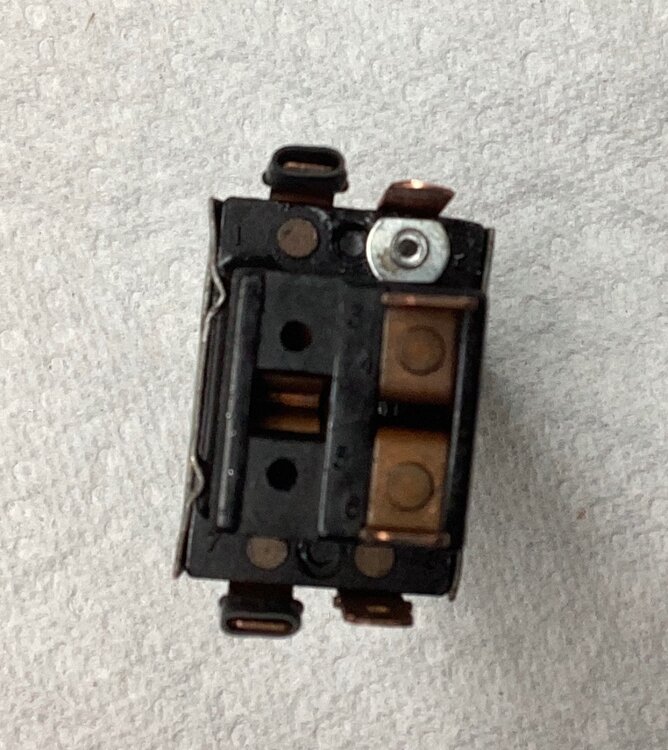
Folks, I wanted to post a picture of the modified 4A wiper switch that Roger provided, after I ruined mine by dropping it (Thanks again Roger!).
You can see the new contact Roger added in position 2. It might be hard to see, but he also covered contacts 1&7 with shrink tubing as these should not be used.
So these are the connection paths of the new switch (see my diagram above for wire locations/colors):
- with the switch pushed all the way in (off) - pins 2&6 connected
- pulled to the first stop - pins 4&6 connected
- pulled to the second stop - pins 4&8 connected
So I guess that’s all for my switch/wiring questions.
I am still waiting for delivery of the 90 degree wiper motor gear from SVC. Once I get that, I’ll hook everything up and give it a try. I’ll post a new topic with my results.
Thanks to all for the help!!!!
cheers,
Jim
-
Thanks!
Jim
-
A friend asked about how to join the TR4/4A forum. I initially was going to send him the link shown in the attached first picture. However when I tried it myself, the page it took me to (second picture), doesn't have a “Community” tab. Is there a different process to join that forum? Or is it only available if you are a TR Registry member?
thanks
Jim


12v cigarette lighter/USB/Speed
in TR4/4A Forum
Posted · Edited by Tr4aJim
It’s the state law in NJ (and I believe in all other states as well) that you must move to the right as quickly as possible - as long as it is safe to do so - to allow emergency/police vehicles to pass (they are trained to pass on the left). It can get a little confusing on barrier divided highways, but seems to work out ok. Whoa to the driver who doesn’t allow a police car to pass!
Jim