


Lebro
-
Content Count
12,011 -
Joined
-
Last visited
Content Type
Profiles
Forums
Calendar
Posts posted by Lebro
-
-
I was thinking
Vulcan years

-
But my reconing you are now 17 !
Bob
-
The main TRR site was down as well
Bob
-
Have not noticed a problem here
Bob
-
No, that was the Beta. 3B is not much different to a 3A, TR4 engine, & gearbox only I think.
-
I have a pair of seats finished in Blue, both in very good condition. (Since replaced with Racetorations ones)
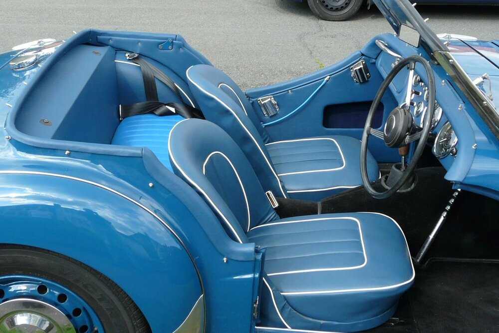
Can take up to date photos if interested.
Bob
-
Also - different throttle linkage, dashboard, glove box, dipswitch support bracket, steering box, pedals are different, but can be adjusted to be near enough, & some of the pipework for brakes, & clutch need to re-routed (or replaced)
As for cost, no idea really.
Bob
-
Do both lights get brighter when brakes are applied ?
If not check wiring goes to the right terminals on the bulb holder. If ok, then:
1st step I would suggest is to swap the bulbs from side to the other & see if the problem follows the bulb,or stays on the same side.
Bob.
P.S. Thanks

-
What he said
")
Bob
-
I think we need a bit more information about it please.
Bob
-
I remember seeing it at Donington in the mid 70's
Bob
-
Nice !
Bob
-
1 hour ago, RogerH said:
Hi Folks,
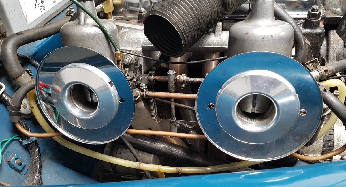
just as an aside, I have the largish round K&N filters on my 4A and found that under certain running conditions the front one would hit the wheel arch.
Looking at various wheel arch shapes I decided to indent the wheel arch - this was surprisingly simple.
A firm bash or two with a round headed rubber mallet produced what I was after. Job done.
Roger
Yep, did that to mine too
Bob
-
3 minutes ago, RogerH said:
I think he is talking about the guide tube, set in the head
Roger
Ah, right. well that's just as well, as I can't find my original rods ! I must have already passed them on to someone else. - Sorry Lehsend
Bob
-
I may have a set of the steel pushrods available, I fitted some special ones which were "adjustable" in length as I had 0.060" removed from the head face.
Will take a look & see if I still have them
Bob
-
I also chose the best version from the above diagram, made my own, & fiited them inside my modified filters (see beginning of this thread)

Bob
-
+2
Bob
-
This is from Harry after fitting the simple dimmer circuit refered to above.
Bob
-
The one with Elvis in it ?
-
Video added to previous post on new construction
-
20 minutes ago, Charlie D said:
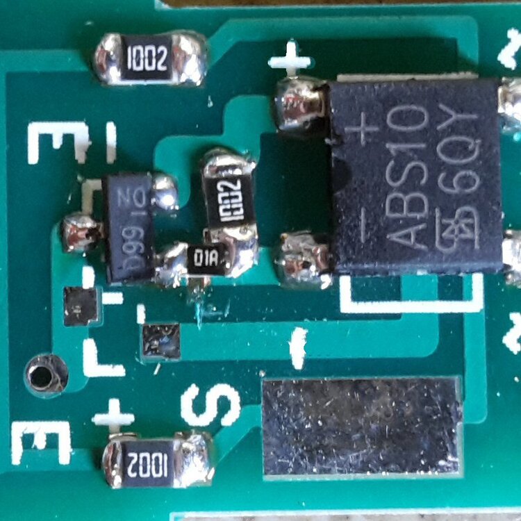
I’ve always kept away from surface mounted stuff, but it’s interesting to see how well it fits in with Veroboard, across the tracks.
Problem I see is that the resistors would just float away when the solder melts and end up where they decided to go, not where you wanted them to go.
Yes, the 0805 size do fit veroboad nicely. Trick is to tin the 1st track generously, then hold resistor with tweezers, & place it in position. Apply soldering iron to fix the 1st end, then apply solder & iron to the other end, & finally a bit more solder on the 1st end. That way it can't move.
If using them on a pcb designed for SM, then you can heat the whole area with a hot air source, & as the solder paste melts the components self align.
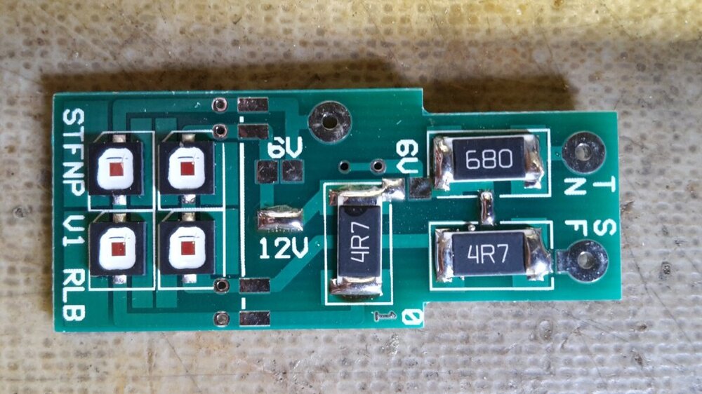
The LED's on the left of this board are soldered on this way (the connections are underneath, so you can't use an iron)
-
Those are 0805 resistors, 1 resistor (100R) on my stop / tail / flash bulbs is 0402 size need my big magnifier for that one !
Don't forget W =V * I (not sure who's law that is, but it's a useful one ! )
-
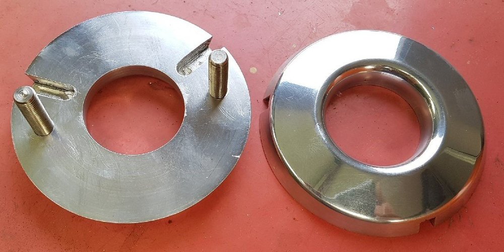
Update to my (adapted) design above, just made a 2nd for a forumite, & used a standard relay, with the circuit outside, also used surface mount resistors to get the board size down.
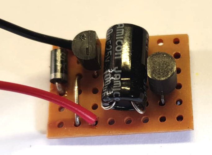
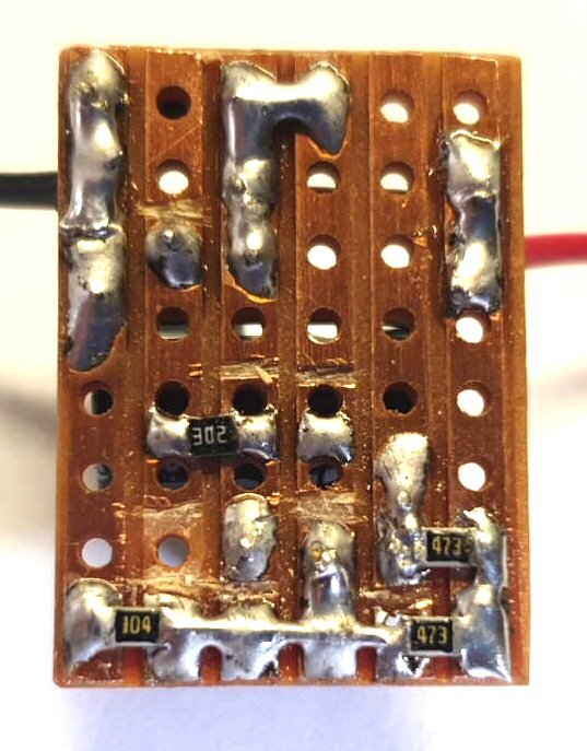

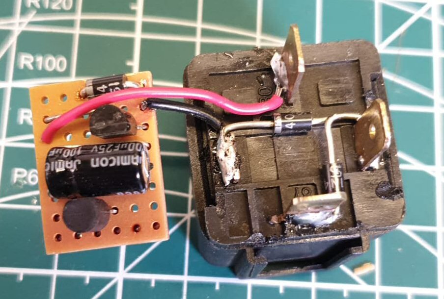
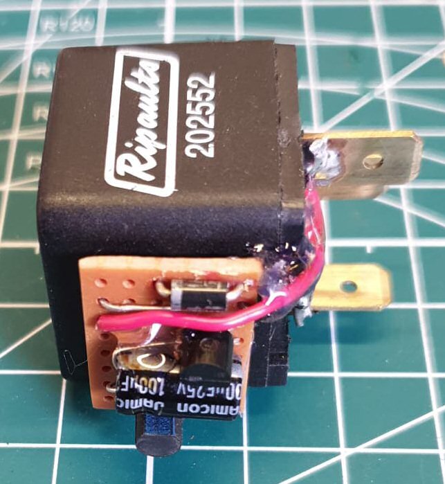
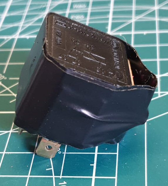 click on to enlarge
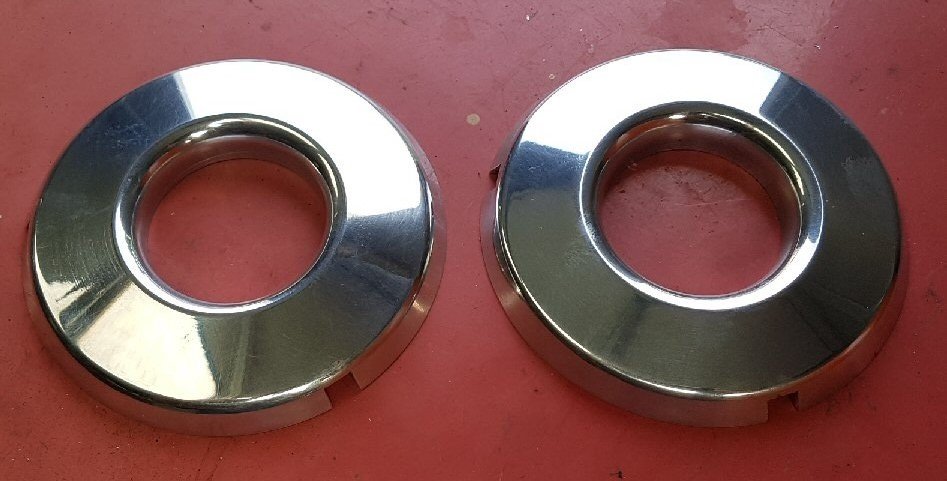
Bob
-
Normal right hand thread so anticlockwise
Bob


Stering box oil
in TR2/3/3A/3B Forum
Posted · Edited by Lebro
You want the extra thick oil specificaly for steering boxes:
https://www.ebay.co.uk/itm/333150463277?var=542171702745 or
https://www.ebay.co.uk/itm/181166424851
Bob