boxofbits Posted August 21, 2016 Report Share Posted August 21, 2016 Morning All I have just offered up the Surrey backlight to my 4a to see how it would line up and initially it would seem at the B Post point of the forward decking it seems wider than the frame. The frame has a superfluous stud just behind the most forward point in each side, so does this suggest it was originally fitted to a TR4? Secondly, I would imagine the fit issue might be due to so many cars having been rebuilt/ repro panels etc by now, and maybe the backlights weren't all the same? Does anyone have any advice on how to overcome this problem? Regards Kevin Quote Link to post Share on other sites
Motorsport Mickey Posted August 21, 2016 Report Share Posted August 21, 2016 (edited) The 4as have a narrower deck section just back from the B post area, it's too help accommodate the wider more bulky hood frame of the 4a when it's folded up. As I understand it the wider deck section as fitted to the original 4 models hasn't been available probably since the 1970s, all replacement panels since being the narrower 4a version which fits and accommodates the TR4 and Tr4a's hoods. The second stud on the backlight which drops inside the 4a narrower deck section is just removed for the backlight section to fit, and the front hole on the narrow deck section above the B posts should have a stud screwed into it's captive nut, the stud protruding up through the backlight front hole and secured with a nut. Will the backlight fit over the B posts if a stud is screwed into those holes ? Mick Richards Edited August 21, 2016 by Motorsport Mickey Quote Link to post Share on other sites
RogerH Posted August 21, 2016 Report Share Posted August 21, 2016 Hi Kevin, the frame may well be a tad wider but I would suggest NOT to try and bend it. The bodywork is quite flexible and I would have thought over the years it may well have moved inwards. Roger Quote Link to post Share on other sites
harrytr5 Posted August 21, 2016 Report Share Posted August 21, 2016 The alloy back lights I believe are all the same.The forward fingers of the rear deck on the TR4 are wider. The only ones available are waisted (slimmer) so you have to grind the stud off one back from the forward point (top of B post).The frame has got a little flex on it and you can persuade into place. Regards Harry Quote Link to post Share on other sites
boxofbits Posted August 21, 2016 Author Report Share Posted August 21, 2016 The frame actually appears to be narrower than the width measured across the car from just behind the doors. If I wanted the top to fit over the forward deck flanges, I'd be looking for 3/8" or so minimum for the b/light to fit over the flange of the forward deck, especially towards the B post area. The forward deck sections to seem to have a slight vertical taper which might help the top to pull down, but not hopefully at the expense of the paintwork. I imagine that when these cars are rebuilt it could be possible to get the dimension across the top of the forward deck out, since there are no reference points at this area, ie roof pillars? Quote Link to post Share on other sites
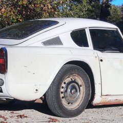
boxofbits Posted August 21, 2016 Author Report Share Posted August 21, 2016 Many thanks for the replies. I have added a few photos showing how far the frame is out. I can't see how the line of the car could be that far out as looking along the car it looks fairly straight both sides and the gaps between the top scuttle sides and door top look parallel. Has anyone got experience with this issue. I am also concerned that spreading the base of the backlight might cause issues with the screen fit? Quote Link to post Share on other sites
boxofbits Posted August 21, 2016 Author Report Share Posted August 21, 2016 If anyone could kindly give me the dimension across the very front outer edge of their Surrey backlight I'd be grateful. Also the measurement across the front inside edges of the chrome pillar cappings please? Many thanks Kevin Quote Link to post Share on other sites
stuart Posted August 21, 2016 Report Share Posted August 21, 2016 Well for a start you need to remove the ally capping piece and the 3 popper studs from both sides or you will never get it to fit and I have had to Portapower Surrey frames out a bit to get them to fit down over the deck (also by the same token I have had to pull the tops of "B" posts in to get them to fit.) Stuart. Quote Link to post Share on other sites
Guest ntc Posted August 21, 2016 Report Share Posted August 21, 2016 (edited) I did not have to remove mine Stuart ? Edited August 21, 2016 by ntc Quote Link to post Share on other sites
boxofbits Posted August 21, 2016 Author Report Share Posted August 21, 2016 Hi Stuart Yes realised I'd have to take the cappings off, but just laid it across the car late last night and could see it wasn't going to fit. I'd imagine there is quite a bit of Spring across the front edges, and looking on the underside the last 8 inches or so are welded in separately. Is a TR 4 any different across the width compared to a 4a? I've got a porta power so that sounds an option, but have you had a problem with the screen fitting when jacking it out a bit? Thanks Stuart Quote Link to post Share on other sites
stuart Posted August 22, 2016 Report Share Posted August 22, 2016 TR4/4a/5/6 are all the same width across between the "B" post tops (in theory though some restos get it wrong.) If your fitting an original window then they will accommodate anomalies in the frame. Stuart. Quote Link to post Share on other sites
boxofbits Posted August 22, 2016 Author Report Share Posted August 22, 2016 Thanks Stuart I think before stretching it I'll have to get a tape measure and check a couple of good TR's to see what they are, say across the 'B' post front inner edges. That way I can get a quick answer as to whether it's the car or the frame, as for all I know the frame might be bent in slightly. Unfortunately I've got no other TR owner near me to get a benchmark from. Regards Kevin Quote Link to post Share on other sites
Rob Salisbury Posted August 22, 2016 Report Share Posted August 22, 2016 Hi Kevin, just measured mine, .... alloy frame been there for around 20 years (previously a soft top fitted) no stretching needed when fitted to a StanPart complete new rear deck, the measurement across the outside edges of the frame at the top of the B posts is 1m 25cm. Hope this helps. Cheers Rob Quote Link to post Share on other sites
Rob Salisbury Posted August 22, 2016 Report Share Posted August 22, 2016 Sorry, correction, the tape was twisted! the measurement is 1m 21cm Rob Quote Link to post Share on other sites
Tom Fremont Posted August 22, 2016 Report Share Posted August 22, 2016 Hi Kevin, I wouldn't worry about bending the frame 3/8". If you have the glass you can trial fit it to get a clue how it will fit with the frame spread a bit. I seem to recall having to put a tourniquet on a frame between the front mooring holes to enable fitting a repro backlight glass. Once in, I relaxed it and it was able to fit the studs and lock it down. They say the tempered glass will flex a little but not the laminated ones. Cheers, Tom Quote Link to post Share on other sites
boxofbits Posted August 22, 2016 Author Report Share Posted August 22, 2016 Rob + Tom Thanks for your replies. Rob I'll measure the backlight as per your dimensions to see how they compare and post again. Logically thinking there is not too much scope for error on the B post upright angle as the door shut defines it to some extent, which is all good with my car. Also the door would be skewed at the front to the line of the front wing vertically if it was that far out, and the deck sections also dictate the width at the back. But an 1/8" outward error each side would mean a 1/4" overall which might give a problem wihen fitting a backlight. Maybe good idea to use a backlight as a jig when rebuilding to ensure it can be fitted if required at a later date? Tom thanks for your advice, and it looks like a bit of tweaking will have to be in order! Stuart has also confirmed that they don't always fit first time and some 'technical adjustment' across the front with a porta power etc might be required! Regards Kevin Quote Link to post Share on other sites
boxofbits Posted August 22, 2016 Author Report Share Posted August 22, 2016 Hi Rob Wondered if you could double check the measurement you gave me earlier please? Across the outside edges at the B post area mine measures 1m 15 cm or 45 1/4" in old money. Thanks Kevin Quote Link to post Share on other sites
harrytr5 Posted August 22, 2016 Report Share Posted August 22, 2016 Kevin you will be surprised how much you can move the frame to get it to fit on top of the B post. If you have the original glass then refit that even if it is scratched. The laminate ones do not like distorted frames. Regards Harry Quote Link to post Share on other sites
Rob Salisbury Posted August 22, 2016 Report Share Posted August 22, 2016 Hi Kevin, the distance between the two anti-burst whatsits is 1m 127cm, the car width just below the frame(It's trimmed don't forget) is 1m110cm, across the inside edges of the trimmed frame it's 1m 109cm and the outside frame edge to edge as it sits on the B post is still 1m 121cm. The photo you have of the nearside frame edge (maybe the camera angle) looks to me as if there is too much inwards curvature, does the glass fit with the frame like that? Cheers Rob Quote Link to post Share on other sites
stuart Posted August 22, 2016 Report Share Posted August 22, 2016 TBH I agree with Rob it does look as if the frame curves in to the front on the left side. Stuart. Quote Link to post Share on other sites
boxofbits Posted August 22, 2016 Author Report Share Posted August 22, 2016 Thanks Rob and Stuart. I think you're both spot on. Thanks for checking that again Rob and I confirm mine is 1m 15cm, which is 6cm too narrow. I haven't tried the glass in yet, but that's around a 2" difference! You are right in that it does take a dive in on the left, so I do wonder if the car took a wallop on the mid left side at some time in its distant past when the backlight was fitted. I can't imagine that damage could've been done in storage or by general mishandling. When it was blasted there was no sign of accident damage, but being bolted to the deck it may have just been forced inwards on impact. Harry- luckily I still have the original glass and as you say the ally should bend back quite easily. I'll have to work out how to straighten it as a porta power across it will just bend it equally both sides, whereas it looks like it might be on one side only. Thanks all for your input. Kevin Quote Link to post Share on other sites
stuart Posted August 23, 2016 Report Share Posted August 23, 2016 (edited) I had to straighten one that had a similar bend and I bolted it down on the correct side and then used the portapower from one side to the other bent side and then pushed it out past where it needed to be and then let it relax back to the right place. it did split slightly on the joint along the back inner join (They are made in 4 pieces) but had it TIG welded up no problem. Luckily had a stripped TR6 shell that I could bolt it to. Stuart. Edited August 23, 2016 by stuart Quote Link to post Share on other sites
boxofbits Posted August 23, 2016 Author Report Share Posted August 23, 2016 (edited) That's a plan Stuart. I could do as you did and bolt it on the good side with longer bolts and plenty of rag underneath it, then a big block of wood or box iron across the inner wing area to spread the load and length of timber to jack against the other front edge. I'll have to keep an eye on it though to make sure it doesn't start pushing the B post out on the opposite side, but I would've thought the frame would move first. As an alternative I could weld up a frame out of 1 1/2" box the same dimensions as the deck to act as a jig, bolt it down and jack one side out. First off I'll need to check it for symmetry by getting a centreline as it might be a little bit out on each side. Regards Kevin Edited August 23, 2016 by boxofbits Quote Link to post Share on other sites

Recommended Posts
Join the conversation
You can post now and register later. If you have an account, sign in now to post with your account.